2.4. Building and Structure Editing
Contents
- Structure Editing
- Structure Positioning and Visualization
- Create Subsets of Atoms
- Mixed Structure Visualization
- Building Crystal Structures
- Editing Crystal Structures
- Void Finder
- Strain the Structure
- Edit Bonds
- Rename Structures
- Automatically Rename Atoms
- Create Copies of Structures
- Molecular Builder
- Attach Fragments
| download: | pdf |
|---|
2.4.1. Structure Editing
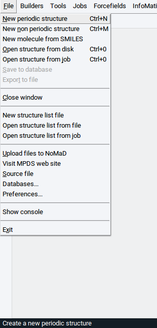
2.4.1.1. Create New Structures
To build new and edit existing structures in simulation cells with periodic boundary conditions (crystal structures, slab surface models, etc.), use the Crystal Builder. The Crystal Builder is opened via File >> New periodic structure For more information, read the section Building Crystal Structures.
To build and edit molecular structures, use the Molecular Builder. The Molecular Builder is available via File >> New non periodic structure. The features of the Molecular Builder are described in the Molecular Builder section.
You can also build molecules via File >> New molecule from SMILES, using the Simplified molecular-input line-entry system (SMILES) notation as follows:
In the upper empty field enter the name of the molecule to identify it within MedeA. In the lower empty field enter the SMILES text string. For instance, to create the caffeine molecule enter the name Caffeine and specify the SMILES text string CN1C=NC2=C1C(=O)N(C(=O)N2C)C. Confirm with OK to display the caffeine molecule in the Molecular Builder.
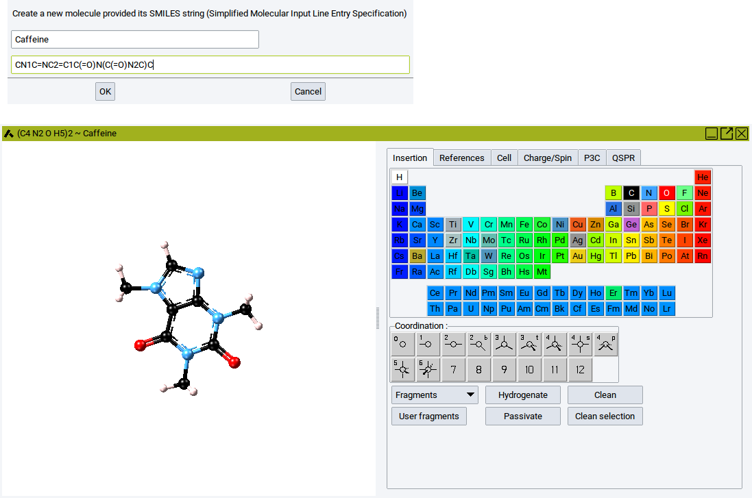
Within the molecular builder the molecule can be further modified (the features of the Molecular Builder are described in section Molecular Builder).
2.4.1.2. Open Existing Structures
In addition to the native sci file format of MedeA, various other formats are supported for reading and importing structure data. To open structure files from disk use File >> Open structure from disk. The supported file formats are shown in the dropdown list below the selection bar Files of type:.
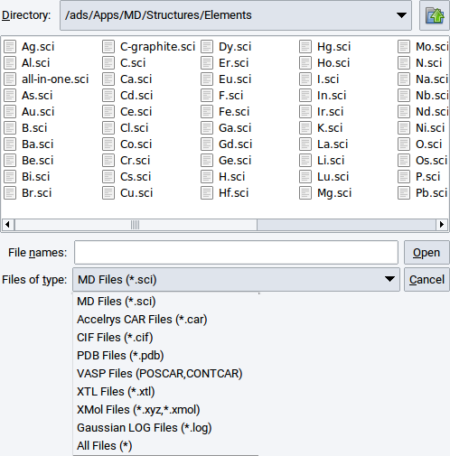
Select an appropriate file format/type, navigate with the file browser to a relevant directory, select the structure file of interest, and confirm with Open.
Structure data can also be loaded from previously performed MedeA jobs stored on an accessible JobServer. Select the relevant JobServer via Jobs >> Select Server, followed by File >> Open structure from job.
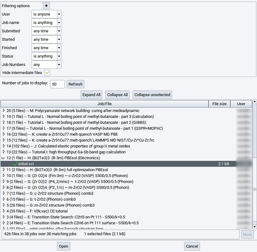
In the resulting dialog, search for relevant sci files by expanding job records.
You can also use the search filters located above the job records after clicking the
![]() icon.
To close the search filters click on the
icon.
To close the search filters click on the ![]() icon.
icon.
Job records can be filtered according to
- User: define the user who owns jobs on the selected JobServer (by default it is your username)
- Job Name: search for strings in the name of jobs or for the entire name
- Submitted: limit the records to the time when jobs have been submitted
- Started: limit the records to the time when jobs have been started
- Finished: limit the records to the time when jobs have been finished
- Status: limit the records to the status of jobs
- Job Numbers: search for structures of jobs with particular numbers
By default the structure retrieval dialog enables the option Hide intermediate files to reduce the number of records. In particular, many intermediate files can be created by jobs that employ MedeA HT, MedeA Phonon, and MedeA Transition State Search. However, in case you want to retrieve intermediate structures disable (untick) the option Hide intermediate files and click on Refresh to show more structure records per job entry. To see the actual sci file records expand relevant records in the list of jobs.
Reduce or increase the value for Number of jobs to display followed by a click on :Refresh to show less or more, respectively, job records.
With InfoMaticA you can also open crystal structures from the approx. 1.1 million records in the MedeA structure databases.
2.4.1.3. Save Structures
Apart from using structures to submit MedeA jobs you can also save created structures either to the Materials Design Database, to disk, or in structure lists.
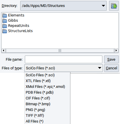
To save structures to disk click on File followed by Export to file. The supported file formats are visible in the selection bar Files of type:.
To store a created periodic structure to the Materials Design Database invoke File >> Save to database. In the appearing window enter the name that the structure should have in the Materials Design Database and a remark about, e.g. how the structure was created. Confirm with OK
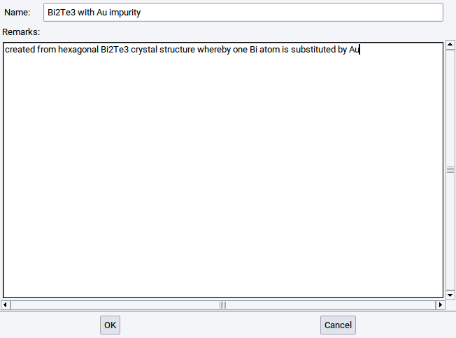
Only periodic structures can be saved to the Materials Design Database, i.e. structures in simulation cells or crystal structures. Structures that were saved to the Materials Design Database can be retrieved with InfoMaticA based on their formulas, names, and remarks, respectively. More information about InfoMaticA is provided in the chapter InfoMaticA of the MedeA manual.
How to save structures in structure lists is described in chapter MedeA HT of the MedeA manual.
Hint
Every structure used to start a MedeA job is automatically stored on the JobServer and can be opened via File >> Open structure from job.
2.4.1.4. Undo / Redo
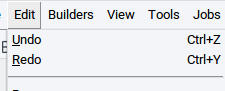
MedeA has options to revert to a state prior to an action (e.g. delete atoms, rotate structures) and to return to the most current state that was achieved after the final action. The former option is called Undo and the latter option Redo. Both options can be invoked in three different ways:
Via the Edit pull-down menu in the main menu bar
With the key combinations Ctrl+Z and Ctrl+Y
With the icons
 and
and  located on the left edge of the
MedeA GUI (see next image).
located on the left edge of the
MedeA GUI (see next image).
2.4.2. Structure Positioning and Visualization
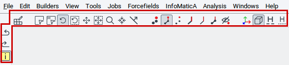
The MedeA GUI has a comprehensive set of options to position structures and to visualize atoms and bonds in different ways. Key options are accessible via the icon bar directly underneath the main menu bar (highlighted by the red frame in the picture below). Hovering the pointer over each icon discloses a brief description in yellow pop-up text.
2.4.2.1. Positioning Options
The icons used to position atoms in the structure viewers are:
 : Switches to the select mode to select one or more atoms. You can select atoms one-by-one
by simply clicking with the pointer on atoms. Dragging the pointer over a collection of atoms lets you
select several atoms.
: Switches to the select mode to select one or more atoms. You can select atoms one-by-one
by simply clicking with the pointer on atoms. Dragging the pointer over a collection of atoms lets you
select several atoms. : Switches to the select molecule mode. If a group of atoms is connected with bonds
(e.g. a molecule, fragment) then the entire group of atoms can be selected by clicking on one atom of this
group.
To select several groups of connected atoms drag the pointer over these groups of atoms.
: Switches to the select molecule mode. If a group of atoms is connected with bonds
(e.g. a molecule, fragment) then the entire group of atoms can be selected by clicking on one atom of this
group.
To select several groups of connected atoms drag the pointer over these groups of atoms. : Enables rotation mode. Within this mode entire structures can be rotated with the arrow keys of
the keyboard or by dragging the pointer.
: Enables rotation mode. Within this mode entire structures can be rotated with the arrow keys of
the keyboard or by dragging the pointer. : Enables to rotate only selected atoms, fragments, or molecules. Within this mode
only selected atoms are rotated and the positions of the un-selected atoms are maintained.
: Enables to rotate only selected atoms, fragments, or molecules. Within this mode
only selected atoms are rotated and the positions of the un-selected atoms are maintained. : Enables translation mode. Within this mode entire structures can be translated with the arrow
keys of the keyboard or by dragging the pointer.
: Enables translation mode. Within this mode entire structures can be translated with the arrow
keys of the keyboard or by dragging the pointer. : Enables to translate only selected atoms, fragments, or molecules. Within this mode
only selected atoms are translated and the positions of the un-selected atoms are maintained.
: Enables to translate only selected atoms, fragments, or molecules. Within this mode
only selected atoms are translated and the positions of the un-selected atoms are maintained. : Enables the zoom mode to decrease or increase the size of structures either with the arrow keys
of the keyboard or by dragging the pointer.
: Enables the zoom mode to decrease or increase the size of structures either with the arrow keys
of the keyboard or by dragging the pointer. : Re-center the active structure to fit into the structure window.
 : If enabled, previously displayed Miller planes can be translated with the arrow keys of the
keyboard or the pointer. Visualize Miller planes via the View menu item.
: If enabled, previously displayed Miller planes can be translated with the arrow keys of the
keyboard or the pointer. Visualize Miller planes via the View menu item.
| Key combination | Action |
|---|---|
| Crtl + Z | undo the last action |
| Crtl + Y | revert undo actions |
| Crtl + A | select all atoms of the active structure |
| Esc | clear the atom selection |
| Del | delete selected atoms |
z +  , ,  , or pointer movement , or pointer movement |
increase or decrease size of the entire structure in small steps |
| Shift + z + , , or pointer movement |
increase or decrease size of the entire structure in large steps |
t +  , , , ,  , , or pointer movement , , or pointer movement |
translation of the entire structure by 0.1 \({\mathring{\mathrm{A}}}\) along the vertical and horizontal axes of the screen |
| Shift + t + , , , , or pointer movement |
translation of the entire structure by 1.0 \({\mathring{\mathrm{A}}}\) along the vertical and horizontal axes of the screen |
| s + t + , , , , or pointer movement |
translation of selected atoms by 0.1 \({\mathring{\mathrm{A}}}\) along the vertical and horizontal axes of the screen |
| Shift + s + t + , , , , or pointer movement |
translation of selected atoms by 1.0 \({\mathring{\mathrm{A}}}\) along the vertical and horizontal axes of the screen |
| Alt + t + , , or pointer movement |
translation of the entire structure by 0.1 \({\mathring{\mathrm{A}}}\) along the axis perpendicular to the screen |
| Alt + Shift + t + , , or pointer movement |
translation of the entire structure by 1.0 \({\mathring{\mathrm{A}}}\) along the axis perpendicular to the screen |
| r + , , , , or pointer movement |
rotation of the entire structure by 1.0 degree around the vertical and horizontal axes of the screen |
| Shift + r + , , , , or pointer movement |
rotation of the entire structure by 10.0 degrees around the vertical and horizontal axes of the screen |
| Alt + r + , , , , or pointer movement |
rotation of the entire structure by 1.0 degree around the axes perpendicular to the screen |
| Alt + Shift + r + , , , , or pointer movement |
rotation of the entire structure by 10.0 degrees around the axis perpendicular to the screen |
| s + r + , , , , or pointer movement |
rotation of selected atoms by 1.0 degree around the vertical and horizontal axes of the screen |
| Shift s + r + , , , , or pointer movement |
rotation of selected atoms by 10.0 degrees around the vertical and horizontal axes of the screen |
2.4.2.2. Visualization Icons
The icons to specify how atoms, bonds, etc. should be visualized are:
 : Draw atoms as large spheres, without bonds
- set sphere sizes in the Spheres tab of the view options
(View >> Options…)
: Draw atoms as large spheres, without bonds
- set sphere sizes in the Spheres tab of the view options
(View >> Options…) : Draw atoms as small spheres, with bonds as cylinders
- set sphere sizes and the thickness of the cylinders via
Change element radii… in the General tab and
in the Bonds tab, respectively, of the view options
(View >> Options…)
: Draw atoms as small spheres, with bonds as cylinders
- set sphere sizes and the thickness of the cylinders via
Change element radii… in the General tab and
in the Bonds tab, respectively, of the view options
(View >> Options…) : Draw atoms as small spheres, without bonds
- set sphere sizes via Change element radii… in the General tab
of the view options
(View >> Options…)
: Draw atoms as small spheres, without bonds
- set sphere sizes via Change element radii… in the General tab
of the view options
(View >> Options…) : Draw bonds as cylinders and isolated atoms as tiny spheres
- set the thickness of cylinders in the Bonds tab of the view options
(View >> Options…)
: Draw bonds as cylinders and isolated atoms as tiny spheres
- set the thickness of cylinders in the Bonds tab of the view options
(View >> Options…) : Draw bonds as lines and isolated atoms as crosses
 : Draw structures in mixed mode - requires selected atoms; more instructions are provided in the
section Mixed Structure Visualization
: Draw structures in mixed mode - requires selected atoms; more instructions are provided in the
section Mixed Structure Visualization : Hide all atoms
 : Show/hide coordinate system/axes in colors; x (red), y (green), z (blue)
- presence can be also controlled via
View >> Axes)
: Show/hide coordinate system/axes in colors; x (red), y (green), z (blue)
- presence can be also controlled via
View >> Axes) : Show/hide cell
- presence can be also controlled via
View >> Cell box)
: Show/hide cell
- presence can be also controlled via
View >> Cell box) : Show/hide detected hydrogen bonds as cylinders - hydrogen bonds are detected based on
definitions in the Hydrogen bonds tab of the view options
(View >> Options…)
: Show/hide detected hydrogen bonds as cylinders - hydrogen bonds are detected based on
definitions in the Hydrogen bonds tab of the view options
(View >> Options…) : Show/hide detected hydrogen bonds as lines - hydrogen atoms are detected based on
definitions in the Hydrogen bonds tab of the view options
(View >> Options…)
: Show/hide detected hydrogen bonds as lines - hydrogen atoms are detected based on
definitions in the Hydrogen bonds tab of the view options
(View >> Options…)
2.4.2.3. View Menu
A range of visualization options can be set in sub-menus of the View item in the main menu bar of the MedeA GUI.
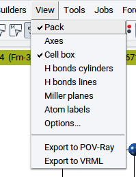
- Pack: Toggle to display atoms that are (slightly) off cell boundaries for periodic systems (only visible in case of structures in a simulation cell, enabled by default)
- Axes: Toggle to display axes of the coordinate system in colors x (red), y (green), z (blue)
- H bonds cylinders: Show/hide detected hydrogen bonds as cylinders - hydrogen bonds are detected based on definitions in the Hydrogen bonds tab of the view options (View >> Options…)
- H bonds lines: Show/hide detected hydrogen bonds as lines - hydrogen atoms are detected based on definitions in the Hydrogen bonds tab of the view options (View >> Options…)
- Miller planes: Displays Miller planes within simulation cells of periodic systems. For information see the section Display Miller Planes.
- Atom labels: Open a window to select labels that you want to display next to each atom. For information see the section Display Atom Labels.
- Options…: The appearing window has several tabs to modify how structures are visualized. For information see the section View Options.
- Export to Povray: Exports current view for structure rendering with the external program Povray For information see the section Create Povray Files.
- Export to VRML: Exports current view to a VRML file. For information see the section Create VRML Files.
2.4.2.4. Display Miller Planes
To display Miller planes invoke View >> Miller planes. Miller planes are defined by their indices h, k, and l (see also Miller Index).
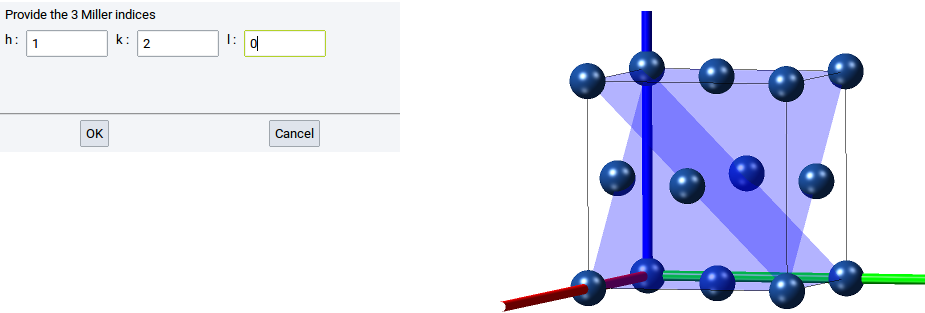
Examples
A Miller plane with any value for h yields a plane that is orthogonal to the x-axis. A (120) Miller plane is orthogonal to the vector (x=1, y=0.5) and parallel to z
Structures can be displayed with more than one Miller plane, as shown in the above image.
Miller planes can be translated when the icon is toggled.
If the Drag Plane mode is enabled then Miller planes can be translated with the arrow keys of the
keyboard or by dragging the pointer.
2.4.2.5. Display Atom Labels
You can tag each atom of a structure with the following labels:
- Atomic number
- Fractional coordinates
- Point
- Wyckoff position
- Atomic symbol (default selection)
- Name
- Site
- Calculated charge
- Number of bonds
- Spin
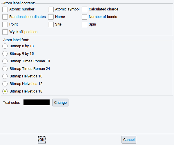
If requested, select another font and Change the color of the atom labels with the options in the lower part of the window.
2.4.2.6. View Options
Invoking View >> Options… brings up a window with 6 tabs to define how structures are visualized.
2.4.2.6.1. General tab
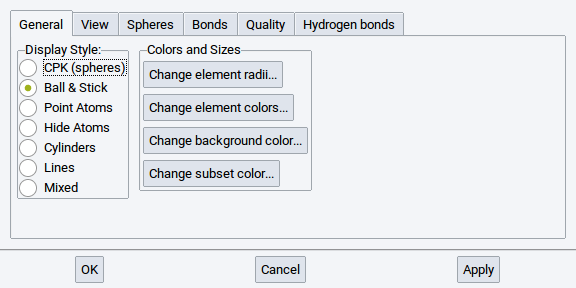
Analagous to the icons below the main menu bar of the MedeA GUI, the Display Style: section allows you to switch between the supported display styles such as CPK (Spheres), Ball & Stick, Point Atoms, Hide Atoms, Cylinders, and Lines. Confirm each change with Apply.
In the Section Colors and Sizes you can
- Change element radii… (for more information, see Section Define Element Radii)
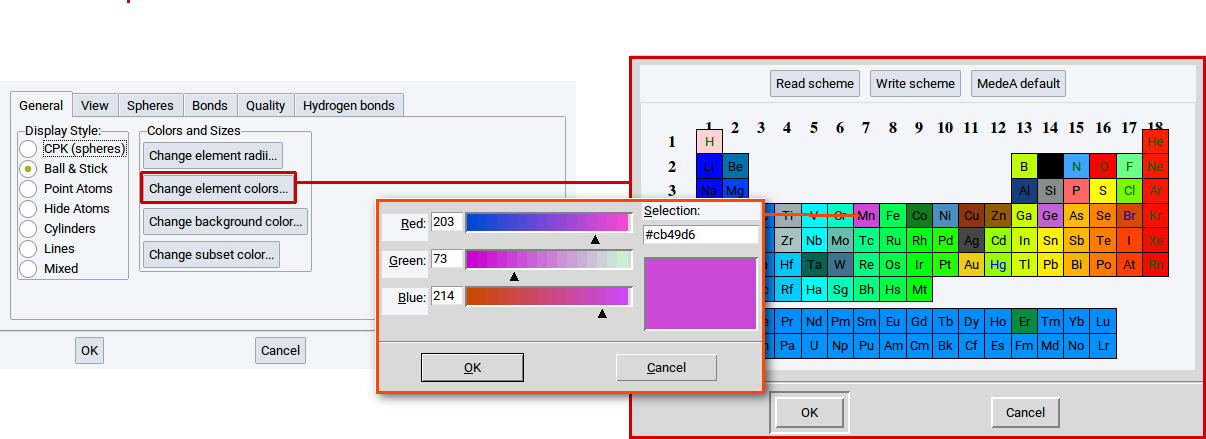
- Change element colors… (for more information, see Section Define Element Colors)
- Change background color… (for more information, see Section Define Background Color)
- Change subset color… (for more information, see Section Define Subset Color)
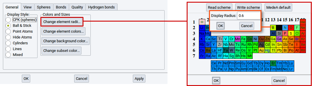
With the option Change element radii… in the General tab of the View Options determine the size of the spheres in the ball & stick visualization style. A click on the option Change element radii… results in the appearance of a window containing the periodic system of the elements (PSE). Click on one of the elements in the PSE for which you want to change the radius, e.g. B (boron). In the next window that appears change the radius and confirm with OK. Also click OK in the window with the PSE. To finally change the radius click on Apply in the in the General tab of the View Options.
With the option Change element colors… in the General tab of the View Options determine the color of the elements in all visualization styles. Click on the option Change element colors… to open a PSE window. Click on one of the elements in the PSE for which you want to change the color, e.g. Mn (manganese). In the next window that appears change the color and confirm with OK. Also click OK in the window with the PSE. To finally change the color click on Apply in the in the General tab of the View Options.
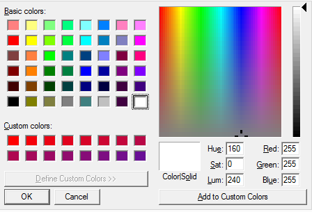
With the option Change Background Color in the General tab of the View Options determine the background color in each structure window.
Click on the option, a color editor appears. In the color editor select the appropriate color, confirm with OK in the color editor, and finally change the color with Apply in the in the General tab of the View Options.
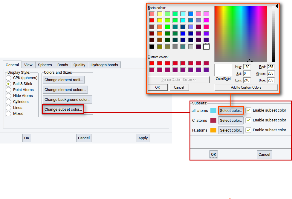
With the option Change subset colors… in the General tab of the View Options determine the colors of atoms of subsets that exist in the active structure.
Click on the option Change subset color… to open a window that summarizes the color settings for each existing subset.
Hint
In case a structure does not have any subset then this window is empty. Read section Create Subsets of Atoms to learn how to create subsets.
Click on one Select color… to bring up a color editor. In the color editor set and create, respectively, a color and confirm with OK. Also click OK in the window with the color settings summary for existing subsets. To finally change the color click on Apply in the General tab of the View Options.
2.4.2.6.2. View tab
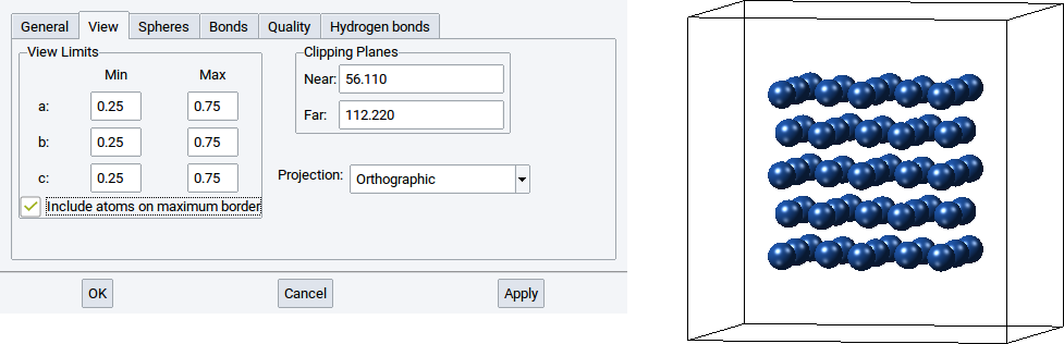
In the View tab you can define which part of a structure should be displayed.
With the View Limits set whether the entire structure should be visualized, only a fraction, or also atoms that go beyond the cell boundaries. By default the view limits for a:, b:, and c: are between 0.0 and 1.0, which means only atoms within the simulation cell and on the edges are shown.
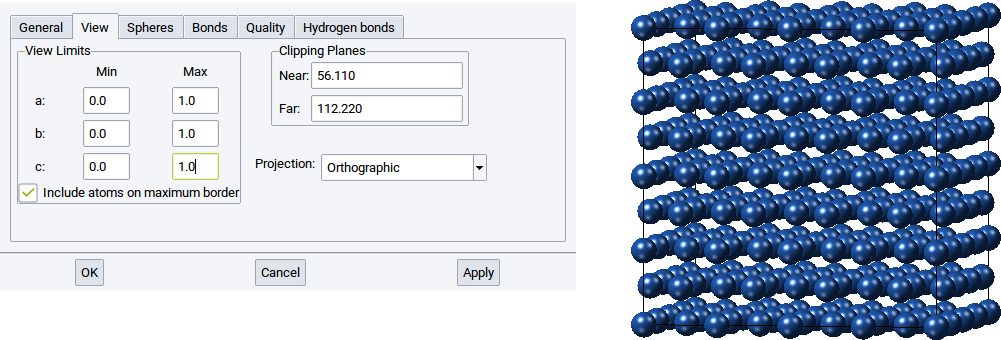
However, if only half of the atoms of the structure should be shown, for instance those around the center of the simulation cell then set the values for Min for a:, b:, and c: to 0.25 and the Max values for a:, b:, and c: to 0.75. Afterwards confirm with Apply to adapt what is displayed in the structure viewer.
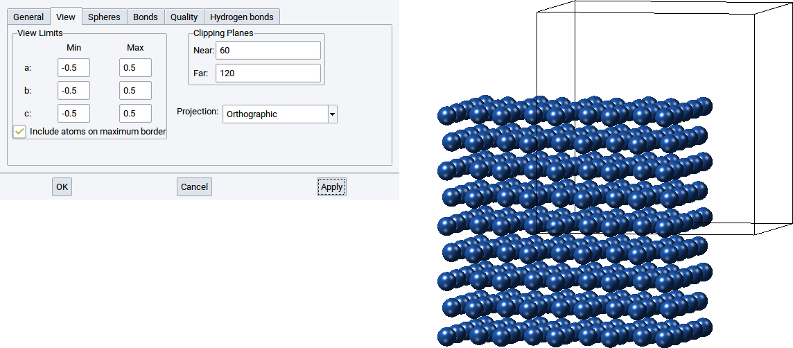
With the View Limits you can also display only a part of structure inside a cell and another part outside the cell. Simply set the values for Min for a:, b:, and c: to -0.5 and the Max values for a:, b:, and c: to 0.5. Afterwards confirm with Apply to adapt what is displayed in the structure viewer.
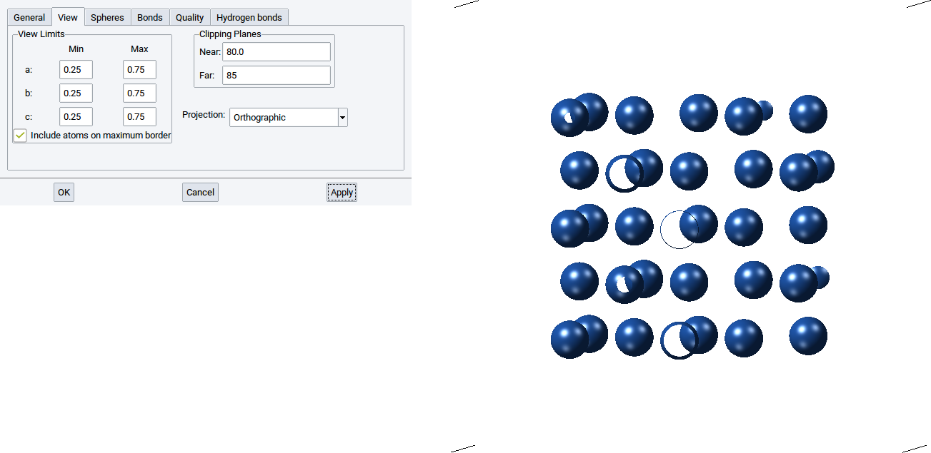
With the values for Near: and Far: of the Clipping Planes define the positions of two translucent planes that are parallel to the screen, whereby one is behind (far) and the other is in front of (near) the structure. The part of the structure between the two clipping planes is displayed and the rest is hidden.
For instance setting a small distance between the two clipping planes results in display of a thin a layer of a structure. Note also that the distance between the clipping planes affects how much of the cell is displayed.
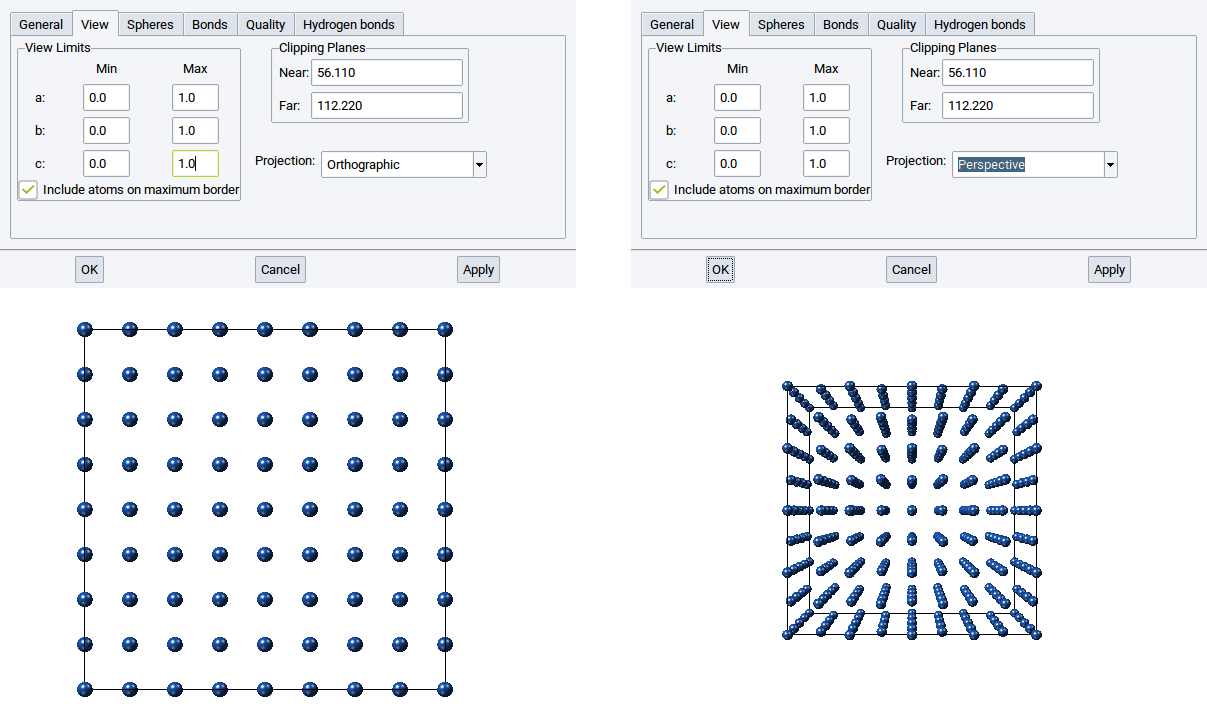
With the Projection you can display a structure Orthographically or Perspectively.
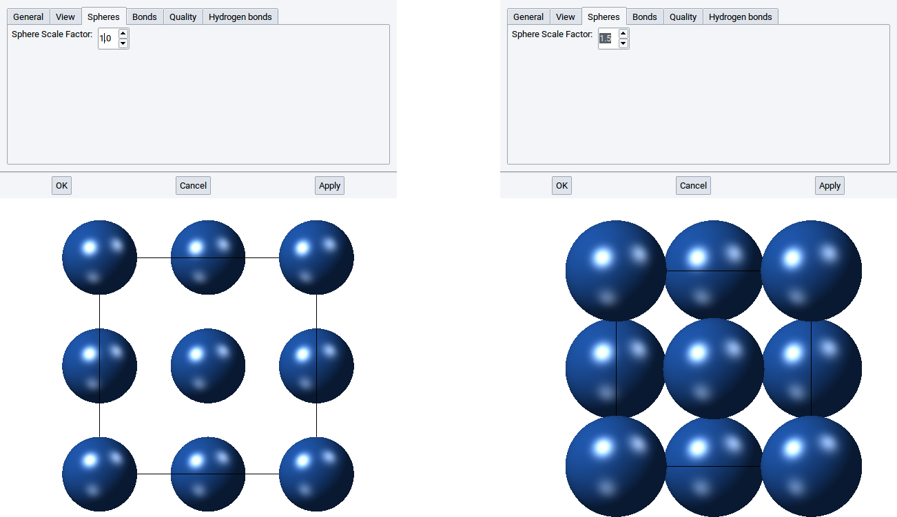
2.4.2.6.3. Spheres tab
In the Spheres tab you can define the size of the atom spheres in the CPK visualization style and the mixed mode. By default the value of the Sphere Scale Factor: is 1.0, i.e. the radii of the spheres in the CPK visualization style are identical to the van der Waals radii of the elements. Obviously, you can increase the spheres by increasing the value of the Sphere Scale Factor: to, for instance, 1.5 and confirm with Apply.
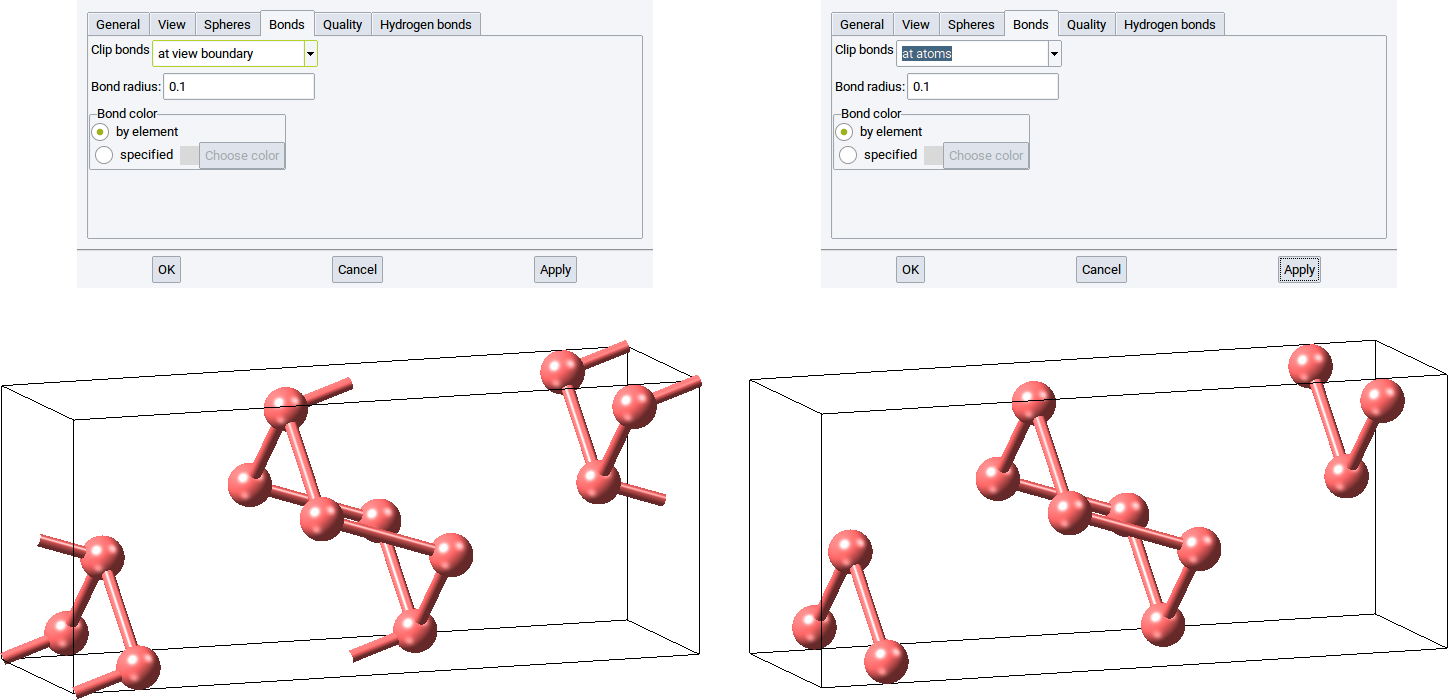
2.4.2.6.4. Bonds tab
In the Bonds tab you can modify how bonds (cylinders) are displayed in the visualization styles ball & stick and cylinders and in the mixed mode. Confirm any modification with Apply.
With the option Clip bonds: you can define whether bonds (connections) between atoms should be visualized between atoms and the cell edges (at view boundary) or hidden if they cross cell edges (at atoms).
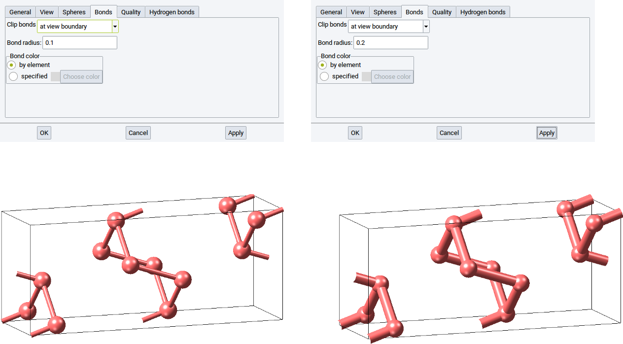
Define the thickness of bonds with the option Bond radius:. The default is 0.1. Increase the radius to 0.2 to double the bond thickness.
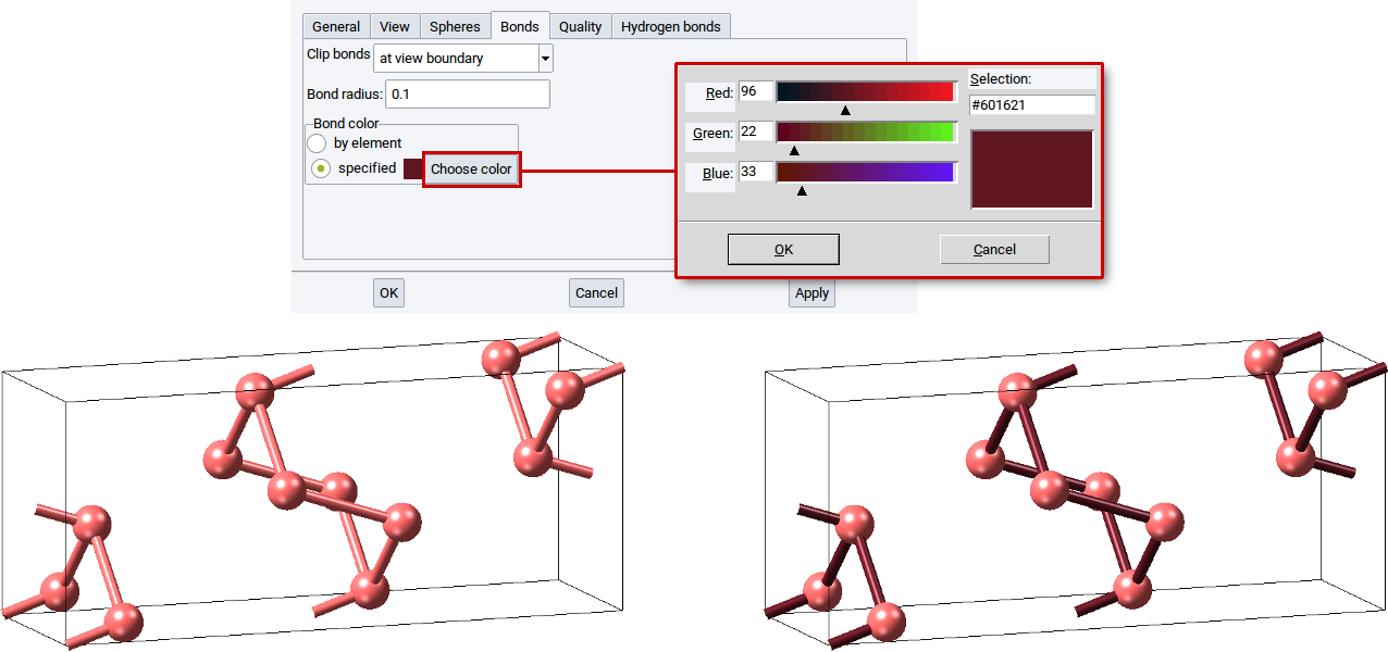
In the section Bond color: define whether bonds should have the same color as the atoms (by element) or should be drawn in another color (specified). For the latter case, click on Choose color and set the color in the color editor dialog. To make the modification definite close the color editor with OK and confirm with Apply.
2.4.2.6.5. Quality tab
Use the Quality tab to define how coarse and fine, respectively, spheres and cylinders are drawn to visualize atoms and bonds of structures.
In case atoms and bonds should be visualized with points, lines, or solid shapes then set the value of the option Style: to Points, Lines, or Solid and confirm with Apply.
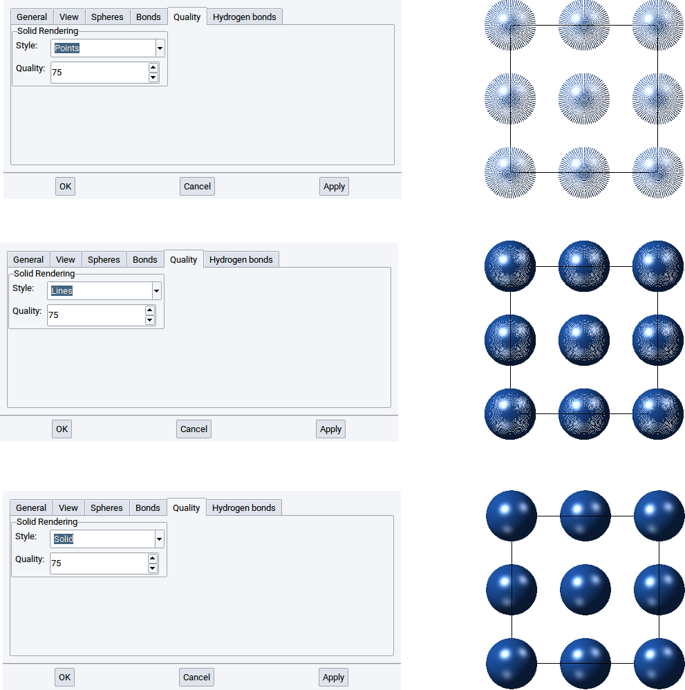
With the Quality: option define how many points, lines, and polyhedra are used to draw atoms and cylinders with points, lines, and solid shapes. The higher the value of the Quality: option the finer and clearer a structure is visualized. Again, confirm any modification with Apply.
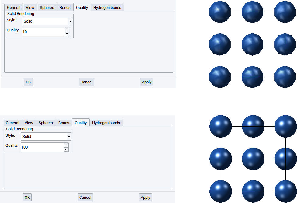
Hint
The computational demand increases in the order of the styles Points, Lines, and Solid and with increasing values of the Quality: option. For instance positioning (rotating, translation) a structure with 1000 atoms visualized with solid shapes takes longer than if atoms and bonds are visualized with points or lines. Hence, when editing and handling structures with 1000 and more atoms we recommend to switch to a less demanding visualization style, for instance to Points. Via File >> Preferences… >> Display Quality you can define size dependent values for style and quality of structures. MedeA already has reasonable pre-defined settings. However, feel free to adapt the Display Quality settings according to your needs.
2.4.2.6.6. Hydrogen bonds tab
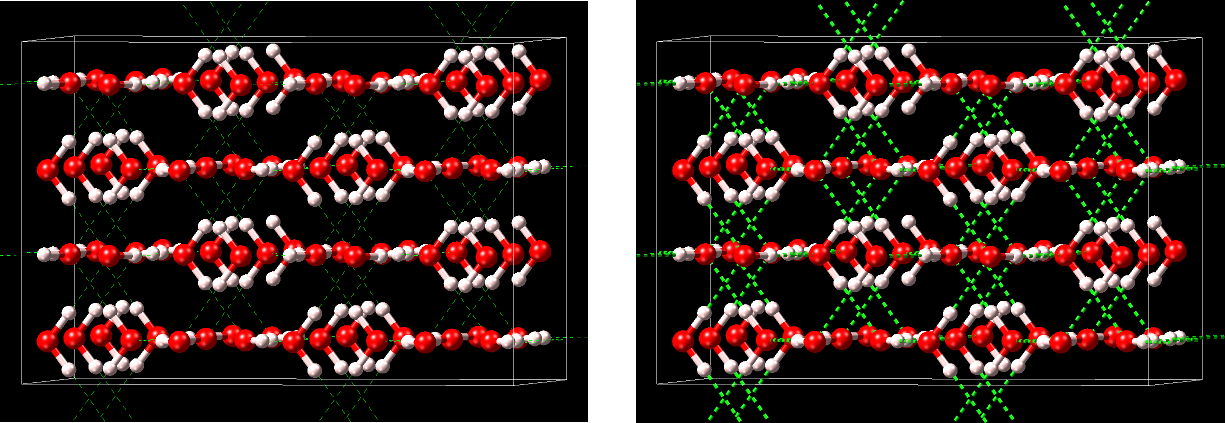
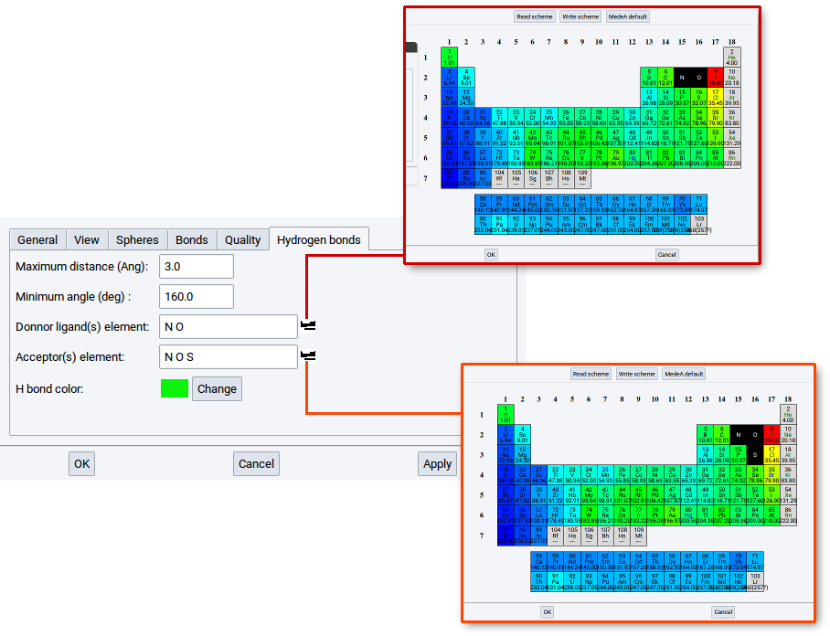
MedeA has the feature to especially visualize hydrogen bonds (H bonds) in structures. Hydrogen bonds are primarily electrostatic interactions between a hydrogen atom, which is covalently bound to one atom or group (donor) and another atom (acceptor). Typical elements for donors and acceptors, respectively, are O, N, and S, among others.
Within MedeA hydrogen bonds are visualized by dashed lines and cylinders between the hydrogen atoms and the acceptor atoms.
You can enable/disable the visualization of H bonds in various ways:
- Click on the icons or in the main icon bar below the main menu bar
- Use View >> H bonds cylinders or View >> H bonds lines
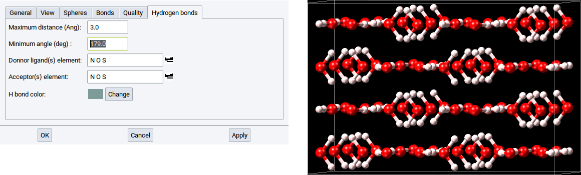
Within MedeA two structural criteria are used to detect H bonds within structures:
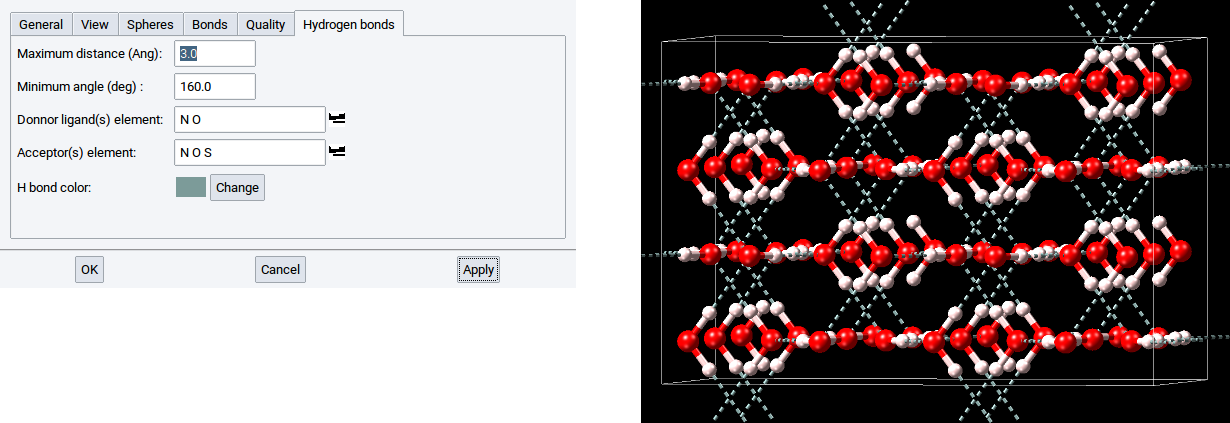
- Maximum distance (Ang): - determines the distance between the donor and acceptor that have a hydrogen atom in-between
- Minimum angle (deg): - determines the angle donor-H atom-acceptor, whereby the H atom is the apex
With the reasonable default values of 3.0 \({\mathring{\mathrm{A}}}\) and 160.0 degrees all meaningful H bonds are captured. For instance, if the value of the Minimum angle (deg) is too close to 180 degrees then no H bond might be detected.
You can modify the list of elements for donors and acceptors.
Simply click on the icons  to open a window with the periodic system of the elements (PSE).
In the PSE select the elements that should act as donors and acceptors, respectively and confirm with
OK.
The newly selected elements should appear in the list of Donor ligand(s) and
Acceptors, respectively.
to open a window with the periodic system of the elements (PSE).
In the PSE select the elements that should act as donors and acceptors, respectively and confirm with
OK.
The newly selected elements should appear in the list of Donor ligand(s) and
Acceptors, respectively.
For instance, if the element S (sulfur) is not present in the list for Donor ligand(s) then no hydrogen bonds can be detected in the crystal structure of solid hydrogen sulfide.
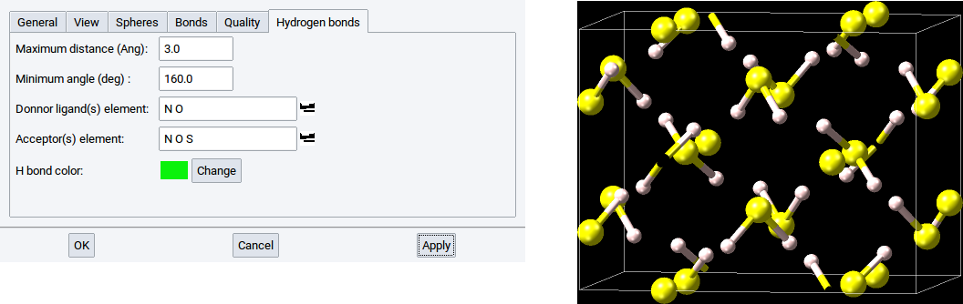
However, if the element S is present in the list for Donor ligand(s) then the hydrogen bond network is detected and visualized on demand.
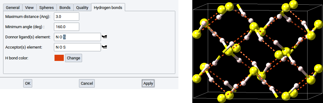
By default, the color of the dashed lines and cylinders, is green. This color can be changed with a click on Change, which opens a color editor to define another color. In the below example the hydrogen bonds are depicted in gray.
Hint
The same options are also accessible via File >> Preferences… >> Miscellaneous.
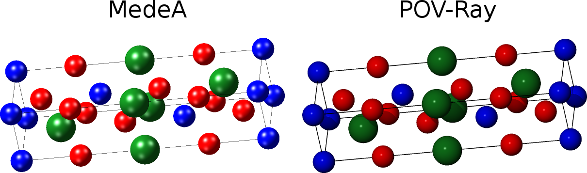
2.4.2.7. Render Structure Views with POV-Ray
MedeA has the feature to create from structure views images and pictures, respectively, that are rendered with the program POV-Ray (Persistence of Vision) which you can obtain from the official POV-Ray Download Page. Once you have installed the POV-Ray executable you should define in the Programs tab of the MedeA preferences (File >> Preferences…) where the POV-Ray executable is located.
To render a view of an active structure open the POV-Ray dialog with View >> Export to POV-Ray).
In the General tab define the
- name and location of the output file
- graphic format
- the size (width, height and unit)
- the resolution
of the final image.
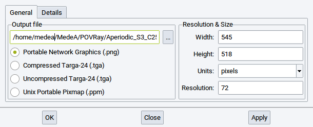
To change the location and name of the POV-Ray input files and the created image file either use the browse button (…) or directly change the string in the text field. For the graphic format chose between one of the supported options. The default size of the image is defined according to the size of the view on your screen. However, you can let make POV-Ray create a smaller or larger image depending on the values that you define for Width: and Height:. Note that the MedeA maintains the ratio of width and height to avoid any distorted structure images. While you change the unit for the dimensions between pixels, inches, and cm also the values for Width: and Height: are adapted.
In case the unit is either set to inches or cm then also the value for Resolution: change the dimensions. An increase of the default resolution of 72 implies a reduction of the dimensions whereas a reduction of the resolution let the dimension of image increase.
In the Details tab define whether and how to depict the simulation/crystallographic cell and set the background color of the final image.
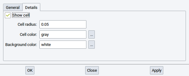
By default the cell is included in the rendered image. To exclude the cell remove the tick-mark from he Show cell option. In case you want to change the thickness of the lines of the image to display the cell, modify the value of the option Cell radius:.
The color of the lines that depict the cell in the image and the color of the background in the image can be modified with a click on the browse button … of the options Cell color: and Background color:, respectively. A click on the button … brings up a window to edit the color.
To start the rendering of the structure view and creation of the image click on Apply.
Hint
The directory that contains the image - as defined in the section Output file - also contains the POV-Ray input files. Feel free to modify and customize the POV-Ray input files according to your needs with the assistance of the POV-Ray documentation and other information available at the POV-Ray site.
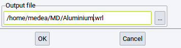
2.4.2.8. Render Structure Views in VRML
MedeA has the feature to create from structure views images and pictures, respectively, that are rendered within the Virtual Reality Markup Language (VRML).
To export a structure view to VRML simply invoke View >> Export to VRML, define the output file, and confirm with OK.
2.4.3. Create Subsets of Atoms
Within MedeA, subsets are sets of atoms that belong to particular molecules and fragments, are of the same element, have the same forcefield atom type, are selected, etc. Subsets are very useful and can even be required to, for example, graphically distinguish groups of atoms with different properties using different visualization styles, to analyse results, or to post-process data from calculations.
To create subsets in periodic structures and molecular structures invoke Subsets >> Create… >> of the Context Menu in the Periodic Structure Viewer and the Context Menu in the Molecular Builder, respectively.
Hint
Click on the Help button to open a comprehensive overview and explanation of the purpose of subsets and the required parameters to create subsets. The following paragraph gives only a brief summary of the options available for creating subsets.
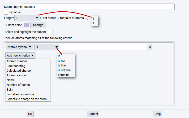
Using the Create subset dialog you can define a subset with the following options:
- Subset name: - is required to identify the subset within MedeA; subsets without a name are not permitted
- dynamic: - if this option has a check-mark then the size and content of the subset can change during its usage within MedeA. Without a check-mark the subset definition is considered to be static
- Length: - the value 1 is for an atom or a group of atoms, whereas 2 is used to create a subset that consists of atom pairs that may be used to define vectors, directions, etc.
- Subset color: - Click on Change to re-define the color of the atoms upon selection of the subset
- Select and highlight subset - tick/enable this option if the atoms of the subset should be selected and highlighted immediately after creation of the subset
Use the following criteria (atomic properties) to select atoms that should constitute subsets:
- Atomic number: number of the element in the periodic system of the elements (e.g. C has the atomic number 6)
- Backboneflag: atoms have this flag in case they are part of a (polymer) backbone (e.g. atoms of molecules have this flag, if the chains were created with the Polymer Builder)
- Calculated charge: charges that were calculated with, e.g. VASP and LAMMPS, respectively
- Atomic symbol: symbol as defined in the periodic system of the elements
- Name: name of atoms as defined in, .e.g the Molecular Spreadsheet
- Number of bonds: amount of bonds/connections to nearest neighboring atoms and next-neighboring atoms
- Spin: magnetic moments of atoms, either initialized via the Magnetic Moments Tab of the Crystal Builder or calculated with VASP
- Forcefield atom type: assigned atom type of the active forcefield (FF) selected via Forcefields >> Choose
- Forcefield charge on the atom: assigned charge based on the assigned FF atom type
For each individual criterion, the available matching attributes are:
- is: is true if the criterion is equal to the defined value
- is not: is true if the criterion is not equal to the defined value
- is like: is true if the criterion partially matches the defined value
- is not like: is true if the criterion partially does not match the defined value
- contains: is true if the criterion contains the defined value (the value must be enclosed with “*”)
An alternative straightforward procedure to define static subsets is based on selecting atoms.
Simply click on the icon to switch to the select mode and select one or more atoms.
Once atoms are selected invoke Subsets >>
Create subset from selection… of the
Context Menu in the Periodic Structure Viewer or
the Context Menu in the Molecular Builder.
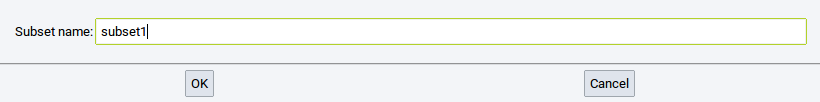
The next required step is to define a Subset name: to identify the subset within MedeA (subsets without a name are not permitted). Finally, confirm with OK.
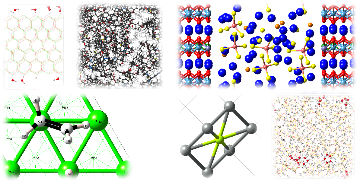
2.4.4. Mixed Structure Visualization
In the mixed visualization mode you can visualize different parts of structures with the styles
- spheres (CPK)
- ball and stick
- cylinders
- lines
It is even possible to hide particular atoms to omit atoms in the visualization without deleting atoms from structures.
A few examples are:
Two steps are required in order to display structures in the mixed visualization mode:
Click on the
icon in the main icon barSelect atoms either by switching to the Select mode
- right-click >> Mode >> Select or click on the icon )
or select previously defined subsets via
- right-click >> Subsets >> Select atoms in subset
- right-click >> Mode >> Select or click on the icon
Once atoms are selected the following items are accessible vie the Selection item of the Context Menu in the Periodic Structure Viewer or the Context Menu in the Molecular Builder:
- Display as CPK: visualize selected atoms as spheres
- Display as Ball & Sticks: visualize selected atoms as balls connected with sticks
- Display as Sticks: visualize selected atoms as sticks only
- Display as Lines: visualize selected atoms as lines
- Hide: do not show selected atoms
Hint
To visualize large parts of structures as cylinders, lines, or even hide many atoms it is recommended to first select the smaller part of the structure that should not be highlighted, then invert the selection via right-click >> Selection >> Invert, and finally use right-click >> Selection >> Display as ….
2.4.5. Building Crystal Structures
In MedeA, you can either build structures from scratch or you can use experimental structures as templates or building blocks.
2.4.5.1. Starting from Bulk Structures in InfoMaticA
Most likely, you will find your system of interest or a closely related structure in one of the MedeA structure databases which can be retrieved with InfoMaticA. From a computational point of view, a crystal structure under ambient pressure and room temperature is close to the low temperature structure determined by a DFT calculation. Starting computations that employ, e.g. DFT methods or interatomic potentials (forcefields) from experimental structure data usually is a very good option. If the system you have in mind is not available in InfoMaticA, try finding a closely related system and modify it by editing and moving atoms and changing lattice parameters.
2.4.5.2. Starting with an Empty Cell
To build a crystal structure manually from scratch you need to know its crystal symmetry, lattice parameters, and atomic positions. If you know the space group symmetry of the system, MedeA will help you in setting up the remaining parameters using symmetry.
To build a crystal structure from scratch, select New periodic structure from the File menu in MedeA’s main window or press the key combination Ctrl-N on your keyboard to bring up the builder window.
You could start adding atoms right now, but it is more efficient to choose the desired symmetry before adding atoms. This way, symmetrically equivalent atoms will be recognized as such and positioned at proper lattice sites.
Right-click into the structure window and select Edit Symmetry… from the context menu.
Select the desired space group in the Symmetry menu and click Apply. For example, to build a structure, select for Centering: Body centered, afterwards in the other selector the space-group Immm, and confirm with Apply.
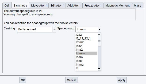
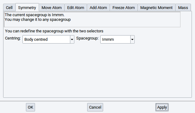
From the moment you apply the symmetry, MedeA displays the current space group of the system.
Hint
All further operations like modifying lattice parameters in the Cell tab and modifying atomic properties in the tabs Add atom, Move atom, consider the newly defined symmetry, unless you explicitly lower the symmetry back to P1, as described below.
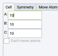
The Cell tab shows only those lattice parameters that can be modified within the symmetry restrictions. In our example, the Cell tab shows only the cell lengths A:, B:, and C:. This is consistent with body centered tetragonal crystal structures which always have cells with angles of 90 degrees.
2.4.6. Editing Crystal Structures
The Crystal Builder lets you change a structure’s symmetry, cell parameters, and atomic positions, degrees of freedom, and masses, add or replace atoms, and create a magnetic structure by setting initial magnetic moments (spins) for specific atoms.
To start the Crystal Builder, right-click into the structure window and select Edit Cell from the context menu or select Edit >> Edit Structure… in MedeA’s main menu.
Hint
The Crystal Builder has three main buttons at the bottom:
- OK: Applies changes and closes the Crystal Builder
- Cancel: Closes the Crystal Builder and discards previously made modifications
- Apply: Applies changes and opens the Crystal Builder for further modifications
2.4.6.1. Cell Tab
The Cell tab lets you change the cell parameters of the currently active structure while considering the current symmetry (space-group). Lower the symmetry to P1 (see below) before trying to change cell parameters in such a way that breaks the current symmetry.
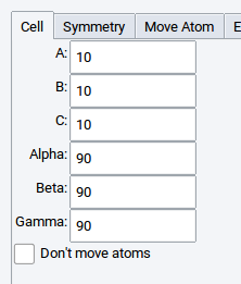
Check the Don’t move atoms box to change the lattice parameters without moving atoms. This can be useful for creating gaps or slab structures or for manipulating cells that contain molecules.
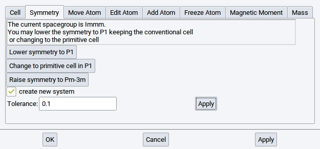
2.4.6.2. Symmetry Tab
This tab shows the symmetry of the currently active structure window. It allows you to lower or raise the symmetry if MedeA finds a higher symmetry group. In addition, if a primitive cell exists for the crystal system, MedeA will show the option Change to primitive cell in P1.
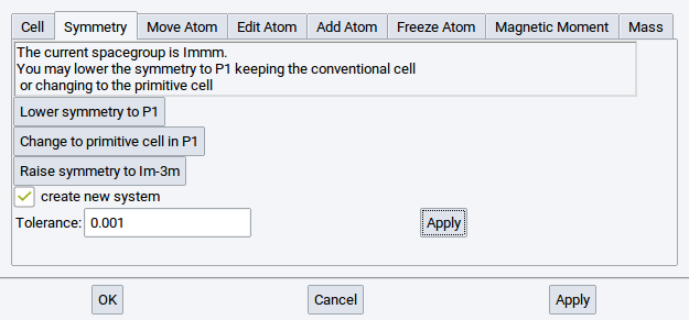
Enable/tick the option create new system to create a new structure window when applying any of the symmetry actions.
Set a Tolerance value to change the precision parameter that MedeA uses in the symmetry finder: MedeA allows for a relative error when checking lattice sites for symmetry. Increase the tolerance to e.g. 0.1 to find more identical positions, i.e. higher symmetry. Click Apply to use the modified tolerance settings.
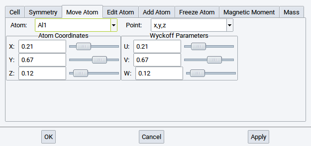
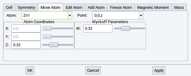
2.4.6.3. Move Atom Tab
Shows the internal degrees of freedom for the current symmetry and lets you move atoms in accordance with that symmetry.
Make your changes and then click Apply to make a change permanent, click Cancel to discard changes. If you would like to make changes that break the current symmetry do the following:
- Lower symmetry to P1 in the Symmetry tab
- Switch to the Move Atom tab and make changes (all degrees of freedom will be available)
- Click on Symmetry to find the new symmetry
- If a new symmetry was found, you may raise the symmetry by clicking Raise symmetry to…
Note
Positions for each atom are given in relative cell coordinates (left) and in Wyckoff symmetry notation (right).
For instance in case of cubic ZnO, neither the Zn atom nor the O atom can be moved without breaking the symmetry.
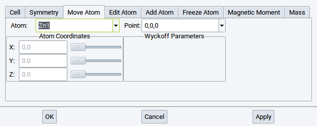
In hexagonal ZnO, on the other hand, both O and Zn have an internal degree of freedom in the z-direction; hence these coordinates can be modified within the high symmetry structures.
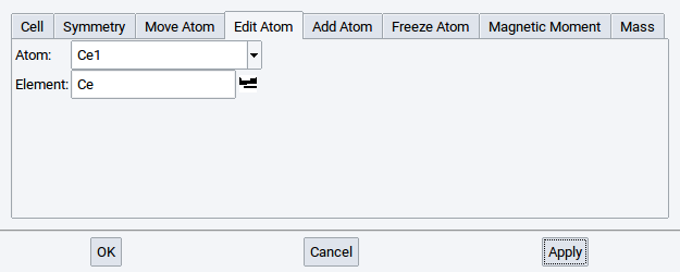
2.4.6.4. Edit Atom Tab
The Edit Atom tab allows you to select an atom from the Atom list and replace it with a different element. Note that atoms on symmetry equivalent positions are replaced as well. Selected atom types are highlighted in pink in the MedeA structure window.
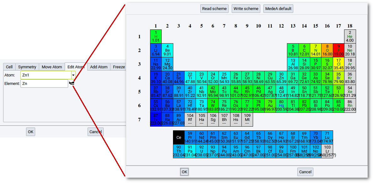
To select an atom type to replace the present atom, you can either type
in the chemical symbol or click on the periodic-table icon () to open a
small periodic table and select an element from the table.
Confirm every change with Apply.
Note
You can also use the Molecular Spreadsheet to exchange elements.
2.4.6.5. Add Atom Tab
To add atoms to the structure, do the following:
- Type the chemical symbol to add an atom for or select from the periodic table (icon )
- Select atomic symmetry positions from the Position menu (left-hand side)
- Use sliders to define position or type in atom coordinates directly: all coordinates are in relative unit cell coordinates
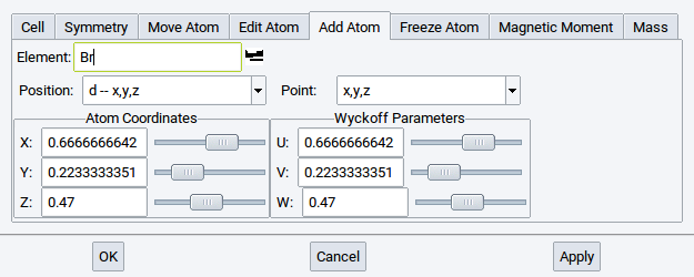
As with all other operations affecting symmetry, Add Atom considers the symmetry of the current system; so multiple atoms will be added automatically if required by symmetry. Their positions are shown in Wyckoff parameters on the right-hand side.
Note
To ignore symmetry constraints, first lower the symmetry of the system to P1.
2.4.6.6. Freeze Atom Tab
MedeA modules such as VASP Phonon, Transition State Search, MT, LAMMPS, etc. change their behavior with “frozen atomic positions”. In structure relaxations and Molecular dynamics simulations with VASP, frozen atoms remain at their initial positions. In Phonon calculations the contribution of “frozen atoms” to the lattice vibrational spectrum (i.e. their force constants) will not be calculated. This is useful if, for eaxmple, just the frequency of a bond stretch of a molecule bound to a surface is required, but not the full phonon dispersion or vibrational spectrum of the molecule-surface system. Most of the MedeA modules issue a warning message if frozen atoms are present in structures.
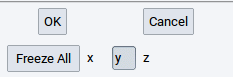
The steps to freeze atomic positions:
- Select an atom from the list of atoms
- Click the x, y, and/or z depending on which directions of atomic motion you want to prevent; click on Freeze all to freeze all spatial coordinates of a selected atom
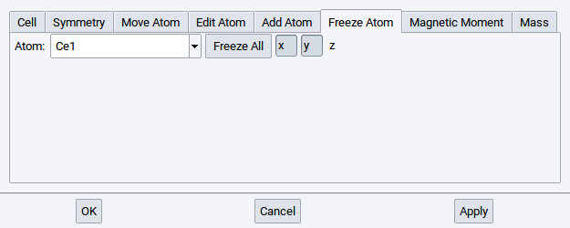
- Confirm with Apply after each change, especially before selecting another atom
Note
Within MedeA you can freeze atoms in various ways:
- Use the Freeze Atom tab
- In a structure window, right-click on an atom >> Atom >> Freeze…
- In a structure window select an atom, a group of atoms, or a molecule, right-click somewhere in the structure window >> Selection >> Freeze selected atoms…
- Open the Molecular Spreadsheet (click on
 ) and select in the
Freeze column which coordinates to freeze (for information read the section about the
Molecular Spreadsheet)
) and select in the
Freeze column which coordinates to freeze (for information read the section about the
Molecular Spreadsheet)
2.4.6.7. Magnetic Moments Tab
Switch to Magnetic Moments to modify initial spin configurations of specific atoms. MedeA considers initial magnetic moments set by the user when running VASP calculations. This action imposes only an initial magnetic structure; the actual value of the magnetic moment is calculated self consistently by VASP.
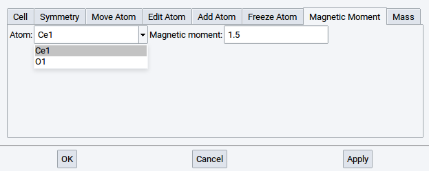
Select an atom from the list and set the magnetic moment (units are \({\mu}\)B). Confirm with Apply after each change.
Note
Within MedeA you can define initial magnetic moments of atoms in various ways:
- Use the Magnetic Moments tab
- In a structure window, right-click on an atom >> Atom >> Magnetic Moments…
- Open the Molecular Spreadsheet (click on ) and set a value in the
Spin column (for information read the section about the
Molecular Spreadsheet)
To break the initial symmetry by imposing atomic magnetic moments, you need to lower the symmetry first to P1 (Symmetry tab), then set magnetic moments, and raise the symmetry again.
Note
The magnetic symmetry is taken into account in the Symmetry tab!
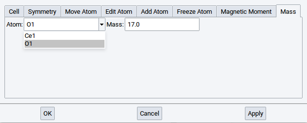
2.4.6.8. Mass Tab
In the Mass tab the mass of each atom can be modified (e.g. for studying isotope effects in dynamics or vibrational analysis).
Note
Within MedeA you can define atom masses in various ways:
- Use the Mass tab
- In a structure window, right-click on an atom >> Atom >> Mass…
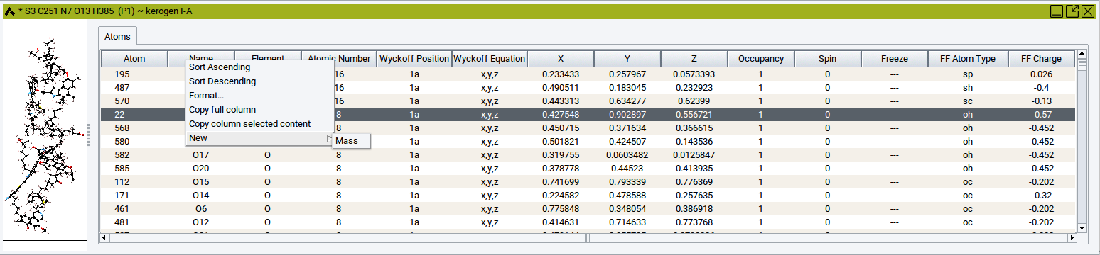
- Open the Molecular Spreadsheet (click on ),
right-click in one of the header cells >> New >>
Mass, scroll to the rightmost column, and defiine the mass in the
relevant cells.
2.4.6.9. Molecular Spreadsheet
Using the molecular spreadsheet you can also visualize and change a number of atomic properties. Use the molecular spreadsheet to
- visualize atomic properties in complex structures
- change the following atomic properties:
- Name
- Element / Atomic number
- Occupancy of positions and sites
- Spin (magnetic moment)
- Freeze state (degrees of freedom)
- Forcefield (FF) Atom Types
- FF Charges
- Atom masses
To toggle the spreadsheet view on/off, click on the spreadsheet icon in
the MedeA icon bar. The currently active structure window splits
into two panels, with the structure on the left and the spreadsheet on the right.
The usual table operations such as sorting and filtering also work in the molecular spreadsheet.
To select an atom, in the structure window, change to selection mode (press the s-key of your keyboard) and left click the atom. Alternatively, simply click on a row in the spreadsheet. Note that table rows and atoms in the graphics are linked, i.e. selecting one will automatically highlight the other. Click and drag your pointer over a range of atoms while keeping the s-key of your keyboard is pressed to select more than one atom at a time.
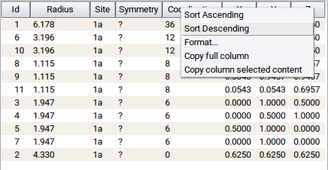
The spreadsheet can be used to visualize constraints (frozen coordinates), atom types, spin states etc. Simply sort the contents of the table columns that contain the relevant property (right-click on column header cells >> Sort Ascending or Sort Descending) and then select the block of atoms within the range of the property you are interested in.
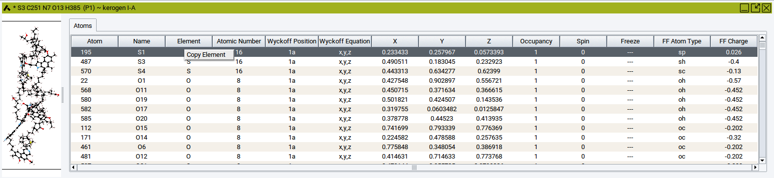
To export data from the spreadsheet (e.g. the atomic coordinates x, y, or z) into another spreadsheet program such as Excel: right-click on the relevant column header >> Copy full column to save the data in the clipboard of your computer. Afterwards, paste the data into your favored spreadsheet program.
To copy data of only single cells: Click into the spreadsheet cell whose content should be copied. Afterwards, right-click in the cell >> Copy ….
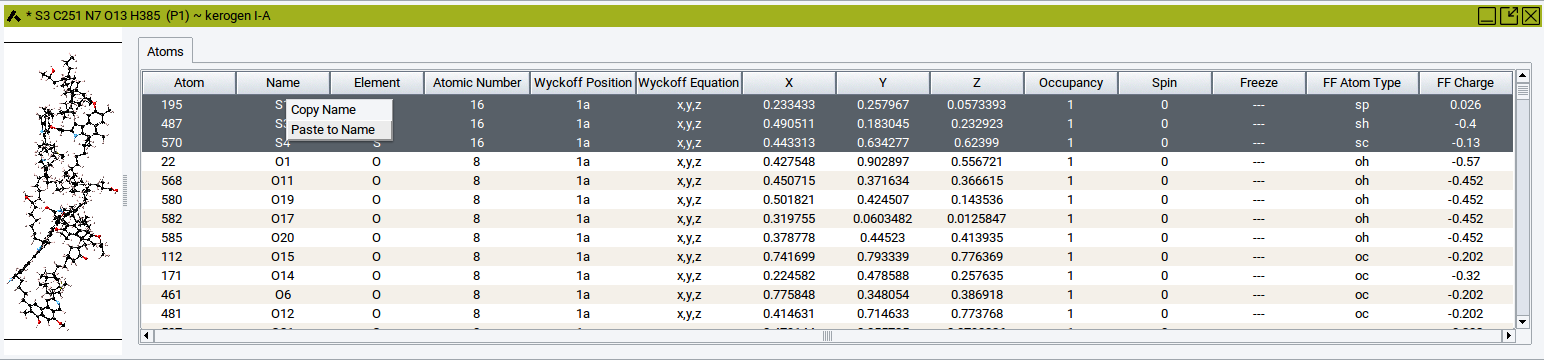
To paste data into one or several cells of the molecular spreadsheet: Click into the spreadsheet cell whose content should be replaced by the copied data. In case the content of other cells should be replaced, then click into other cells while pressing the Crtl key or Shift key of the keyboard. These actions highlight cells in dark gray. Afterwords, right-click in the highlighted cells whose content should be replaced >> Paste ….
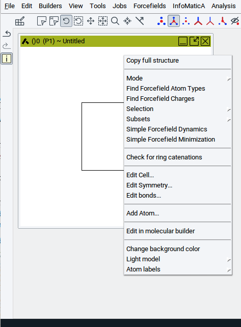
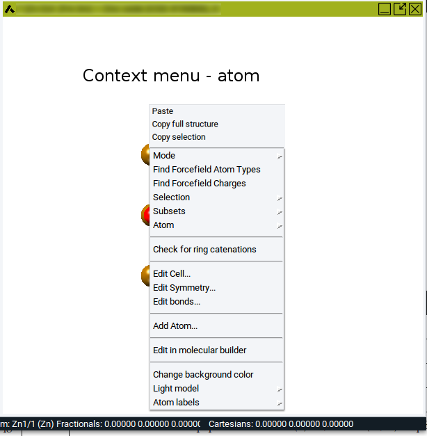
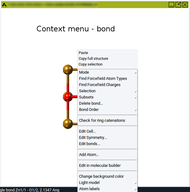
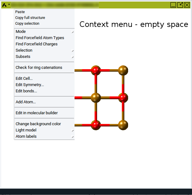
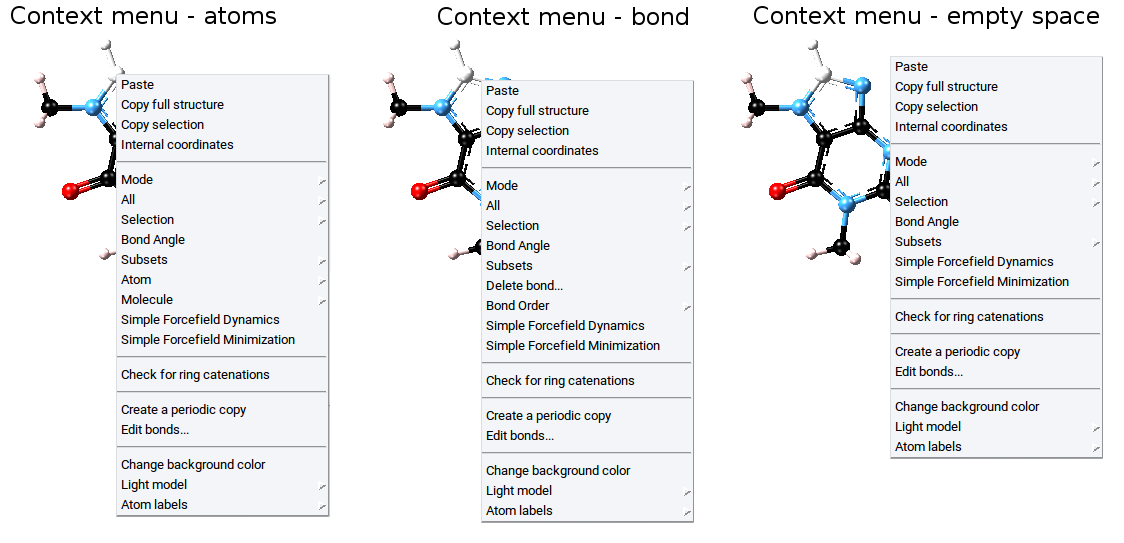
2.4.6.10. Context Menu in the Periodic Structure Viewer
In general, the context menu of a periodic structure window is opened with a right-click somewhere in the structure window. However, the displayed menu items depend on whether the pointer is positioned on an atom, a bond, or empty space (anywhere else in the structure window), and whether structures have the space group symmetry P1 or the symmetry of any other space group different from P1.
The following images show context menus for crystal structures which have the space group P1:
Transferring Atoms and Fragments Between Structures
With the following menu items it is possible the transfer entities (single atoms, groups of atoms, molecules, and fragments) from one structure into other structures.
- Paste: introduce previously copied atoms
- Copy full structure: creates a copy of the entire structure, including bond information, atom type, and other atomic properties
- Copy selection: creates a copy of selected atoms of a structure, including bond information, atom type, and other atomic properties
Action Modes
With the Mode: menu item change the action mode between select, rotate, translate, and zoom (also available from the MedeA icon bar)
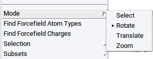
- Select: Select atom(s) by clicking on atoms one-by-one or drag the pointer over a relevant region with atoms; selected atoms appear white
- Rotate: In this mode the entire structure can be rotated
- Translate: In this mode the entire structure can be translated (moved)
- Zoom: Zoom in/out by moving the pointer or using the arrow keys of the keyboard
Assign Forcefield Parameters
- Find Forcefield Atom Types: Assign forcefield (FF) atom types to all atoms based on the selected forcefield (check the selected forcefield with the main menu item Forcefields >> Choose)
- Find Forcefield Charges: Assign forcefield (FF) charges to all atoms based on the selected forcefield and assigned FF atom types (check the selected forcefield with the main menu item Forcefields >> Choose)
Selection of Atoms and Fragments
With the menu item Selection either select all atoms of a structure, clear atom selections, or modify structures based on the selected atoms.
Note
All the following items - except Select all (Crtl-A) - require previously selected atoms!
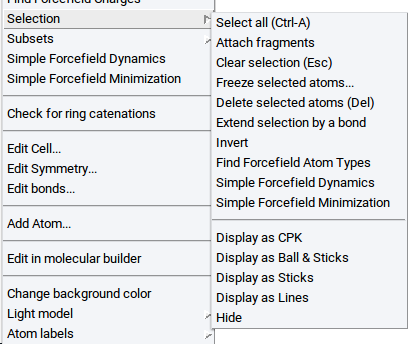
- Select all (Ctrl-A): Selects all atoms; can be also invoked with the key-stroke Ctrl-A
- Attach fragments: bind atoms or molecules to previously selected atoms (more information is provided in the section Attach Fragments)
- Clear selection (Esc): Unselect all atoms; can also be invoked with the Esc key of the keyboard
- Freeze selected atoms…: Sets structural constraints; useful for relaxations, molecular dynamics simulations, and selective vibrational analysis (for more information see the description of the Freeze Atom Tab of the Crystal Builder)
- Delete selected atoms (Del): Erases selected atoms completely; can also be invoked with the Del key of the keyboard
- Extend selection by a bond: Expands selections to neighboring atoms and atoms connected by bonds
- Invert: select all un-selected atoms and de-select all previously selected atoms
- Find Forcefield Atom Types: Assign forcefield (FF) atom types to selected atoms only based on the selected forcefield (check the selected forcefield with the main menu item Forcefields >> Choose)
- Simple Forcefield Dynamics: Evolves selected atoms in 100 molecular dynamics steps, employing a simple forcefield
- Simple Forcefield Minimization: relaxes selected atoms, employing a simple forcefield
Note
The following three menu items appear only if a particular number of atoms are selected.
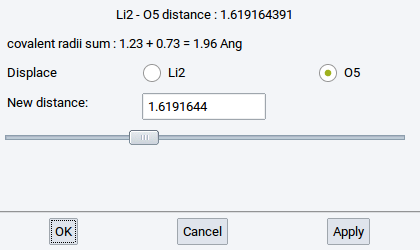
- Distance: Change the distance between two selected and connected (bonded) atoms
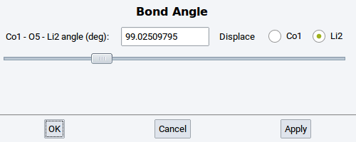
- Angle: Change the angle between three selected and connected (bonded) atoms
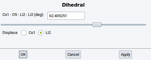
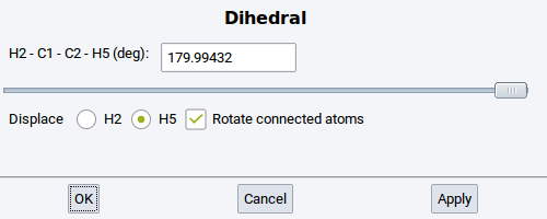
- Dihedral: Change the torsional angle between four selected and connected (bonded) atoms
Note
All the following items require enabling the mixed visualization mode (click on icon )
- Display as CPK: visualize selected atoms as spheres
- Display as Ball & Sticks: visualize selected atoms as balls connected with sticks
- Display as Sticks: visualize selected atoms as sticks only
- Display as Lines: visualize selected atoms as lines
- Hide: do not show selected atoms
Subsets
Within MedeA subsets are sets of atoms that belong to particular molecules and fragments, are of the same element, have the same forcefield atom type, are selected at the same time, etc. Subsets are very useful and required to, for instance, graphically distinguish groups of atoms with different properties using different visualization styles, to analyse results, or post-process data of calculations. With the Subset context menu item you can create and edit subsets.
Note
All the following items - except Create… or Create subset from selection… require previously created subsets or previously selected atoms, respectively.
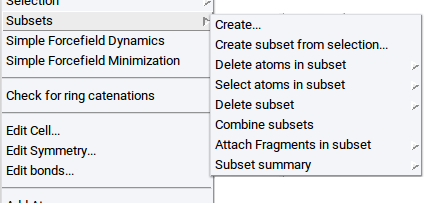
Create…: opens a dialog to specify how a subset should be created (for more information see the section Subsets)
Create subset from selection…: opens a new window to define the name of the subset (for more information see the section Subsets)
Delete atoms in subset: Delete all atoms that form the subset and the subset itself
Select atoms in subset: Select all atoms that define a subset
Delete subset: Delete the subset definition but keep the atoms
Combine subsets: Create a new subset by combining two or more existing subsets
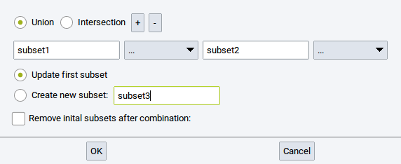
- Union: the new subset encompasses all atoms that belong to the subets that should be combined
- Intersection: the new subset encompasses only atoms that belong to all of the subsets that should be combined
- +: add empty entries/fields (
 ) to define more subsets that should be combined
 - -: remove empty and filled fields from the collection of subsets that should be combined
- Update first subset: let the first subset be the combination of all subsets
- Create new subset: : Combine all relevant subsets in a new subset; define
the name in the empty field (e.g. subset3)
- Remove initial subsets after combination:: Delete the definition of subsers that should be combined
Attach Fragments in subset: Connect molecular fragments to atoms of a subset (more information is provided in the section Attach Fragments)
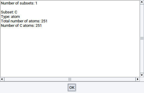
Subset summary: Show a summary of existing subsets in an extra window
Edit Atom Properties
The Atom context menu item appears upon right-clicking with the pointer over an atom
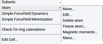
- Move…: Opens the Move Atom Tab of the Crystal Builder
- Edit…: Opens the Edit Atom Tab of the Crystal Builder
- Delete atom: Deletes the atom under the pointer
- Freeze atom: Opens the Freeze Atom Tab of the Crystal Builder
- Magnetic moments…: Opens the Magnetic Moments Tab of the Crystal Builder
- Mass…: Opens the Mass Tab of the Crystal Builder
Create or Delete Bonds
Note
The following menu item only appears if the structure has bonds and if the right-click is invoked over a bond.
- Delete bond…: Deletes the bond underneath the pointer
Note
The following menu item only appears if two atoms ar selected.
- Create bond…: Create a bond between two previously selected atoms.
Modify Bond Order
Note
The following menu item only appears if the structure has bonds and if the right-click is invoked over a bond.
With the menu item Bond Order you can change the order of the bond underneath the pointer
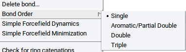
- Single: define a single bond
- Aromatic/Partial Double: Define an aromatic or partial double bond, respectively
- Double: Define a double bond
- Triple: Define a triple bond
Check Macromolecules
- Check for ring catenation: Determine whether molecule bonds/chains go through rings and loops of other molecules (very important to avoid ring catenation, especially in realistic polymer models and polyaromatic systems)
Edit Crystal Structures
- Edit Cell: Opens the Cell Tab of the Crystal Builder
- Edit Symmetry: Opens the Symmetry Tab of the Crystal Builder
- Edit bonds: Opens the Edit Bonds dialog and lets you recalculate the bonds
- Add Atom: Opens the Add Atom Tab of the Crystal Builder
Convert Periodic Structures Into Molecules and Clusters
- Edit in molecular builder: Transfers the structure to the Molecular Builder
Increase Graphical Contrast
- Change background color Changes the background color of all structure windows (for more information read the Section Define Background Color)
Illumination of Structures
With the menu item Light model define how structures are illuminated.
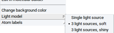
- Single light source
- 3 light sources, soft
- 3 light sources, shiny
Tag Atoms With Labels
With the menu item Atom labels define in sub-menus which atomic properties should be displayed as labels next to each atom
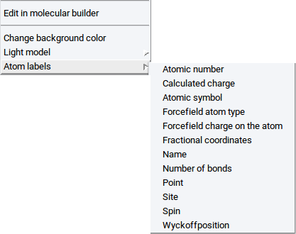
- Atomic number: Display the atom index in the structure
- Calculated charge: Display the charge that was calculated with e.g. VASP
- Atomic symbol: Display element symbol
- Forcefield atom type: Display assigned forcefield atom type
- Forcefield charge on atom: Display assigned forcefield atom charge
- Fractional coordinates: Display fractional coordinates of atoms
- Name: Display assigned names of atoms
- Number of bonds: Display number of connections to other atoms
- Point: Display points of atoms
- Site: Display crystallographic site of atoms within the assigned space group symmetry
- Spin: Display magnetic moment of atoms
- Wyckoff position: Display crystallographic Wyckoff position of atoms within the assigned space group symmetry
2.4.7. Void Finder
2.4.7.1. Introduction
With the MedeA’s Void Finder aka Find Empty Space you can analyze structures in a periodic simulation cell (e.g. crystal structures) regarding empty (interstitial) space in which atoms or molecules can be located. The Void Finder algorithm divides the cell into so-called Voronoi cells around each atom. A Voronoi cell is defined to be the volume enclosing all points that are closer to the central atom than to all other atoms.
The Void Finder module positions non-overlapping spheres at the vertices of the resulting polyhedral grid and maximizes their radii. In doing so the physical size of different atomic species is taken into account through a set of covalent radii (currently fixed). Note that the MedeA Void Finder changes the sphere size to make them non-overlapping. [1]
2.4.7.2. Void Finder Features
The following features are available for the Void Finder:
- Find and display the largest possible void spheres on the vertices of a Voronoi mesh
- Display local coordination and symmetry of voids
- Insert atoms on void centers
- Hide/display all/selected voids
- Sort void table by radius, site ID, symmetry, etc.
2.4.7.3. Void Finder Usage
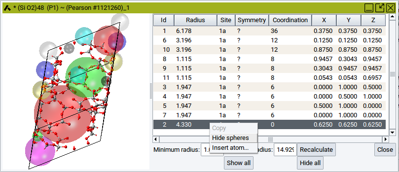
To use the Void Finder activate a structure window that contains a periodic structure and invoke Edit >> Find empty space…. Depending on the size of the structure and the symmetry the structure window splits into two parts within a few seconds (in case of structures with more than 500 atoms the entire process can also take several minutes). The left part displays the structure together with colored translucent spheres where the Void Finder has found empty space. Crystallographically identical voids are displayed in the same color. The right panel displays a table with the properties of the translucent spheres.
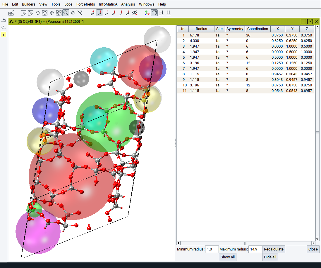
Each sphere is characeterized by
- an ID
- a Radius
- a Site id
- a Symmetry label
- a Coordination
- the fractional X, Y, and Z coordinates
As in other tables used within MedeA the table content and, hence, the sphere properties can sorted in ascending or descending order. Simply right-click on one of the header column cells (e.g. that for Coordination) >> Sort Descending.
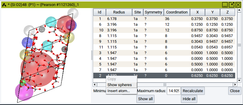
You can hide or show individual spheres by clicking into one of the table rows (to highlight), followed by right-click >> Hide spheres and right-click >> Show spheres, respectively.
To hide all spheres and show all spheres again use the relevant buttons Hide all and Show all, respectively, which are located beneath the table.
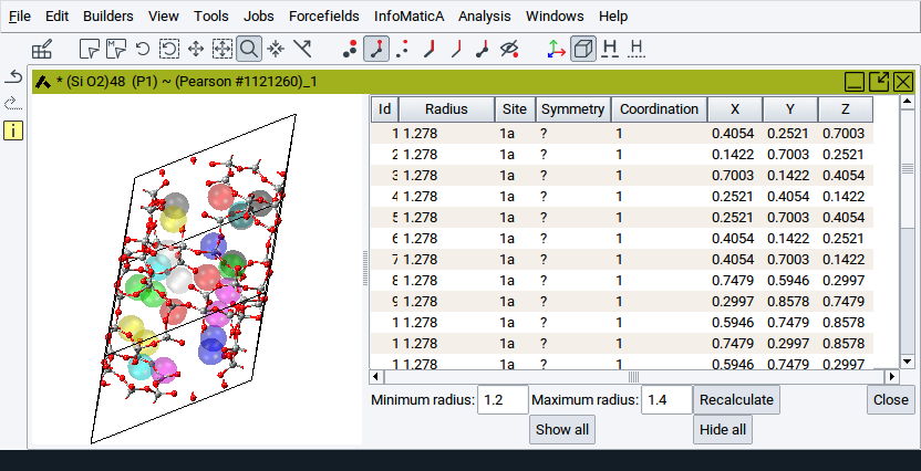
To reduce the number of spheres that are considered and shown, adjust the values for the options Minimum radius: and Maximum radius: followed by a click on Recalculate.
- Minimum radius: Gives a lower threshold for the void radius. No voids with radii smaller than the minimum radius will be shown in the table.
- Maximum radius: Upper threshold for the void radius. No voids with radii larger than the maximum radius will be shown in the table.
Hint
It might happen that the voids are so small that they are non-compliant with the minimum radius. In such cases an information panel pops up and no spheres are displayed.
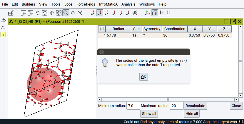
In those cases, Recalculate with a Minimum radius smaller than given in the information panel. This will display voids on interstitial sites.
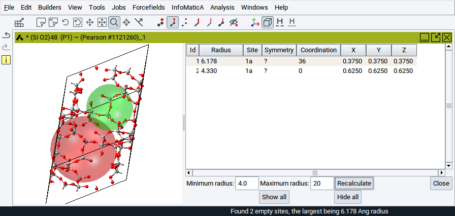
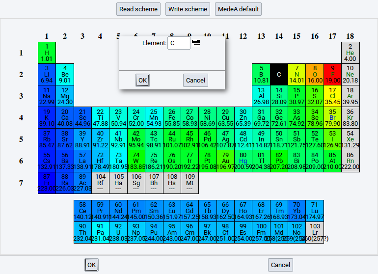
If you want to insert an atom onto the center of a sphere:
- Right-click onto the relevant row in the table >> Insert atom
- In the dialog either enter the element symbol of the atom that should be inserted or
click on the periodic-table icon () to select an element
- Comfirm with OK
To close the Void Finder and return to the original structure window click on Close.
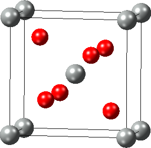
2.4.8. Strain the Structure
With Edit >> Strain the structure… you can deform the simulation cell of a periodic structure by applying a general engineering strain, provided the space group is P1:
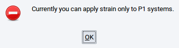
Hint
To apply an engineering strain, lower the symmetry of the structure to P1 with right-click >> Edit Symmetry… . For more information see Section Symmetry Tab
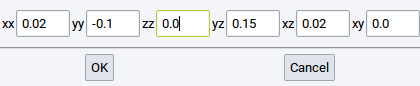
In the dialog, set the six independent elements of the dimensionless engineering strain (xx, yy, zz, and yz, xz, xy) and apply the chosen strain with OK.
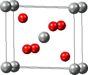
An alternative way to strain crystal structures is to change their cell parameters (length and angle) via the Cell Tab of the Crystal Builder which can be opened with right-click >> Edit Cell….
2.4.9. Edit Bonds
Information about bonds (interatomic connections) is essential for force field (FF) methods (LAMMPS and GIBBS), and very useful for creating and understanding structures for VASP, MOPAC, and Gaussian. Bonds can be created and deleted with the Bond Editor dialog which can be invoked from Edit >> Edit bonds… or right-click >> Edit bonds….
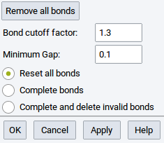
- Remove all bonds: delete all bonds between atoms; the result is a structure with spheres only
- Bond cutoff factor: Two atoms closer than the sum of their covalent radii multiplied by the dimensionless Bond cutoff factor are considered to share a bond.
- Minimum Gap:: MedeA uses Voronoi tessellation to find nearby atoms without considering atoms in higher coordination shells. You can still add a small value define by this option (value in \({\mathring{\mathrm{A}}}\)) to discern first and second coordination shell.
- Reset all bonds: Delete all existing bonds and compute new bonds according to the defined Bond cutoff factor and Minimum Gap
- Complete bonds: Keep existing bonds (including bond orders, main interest of this option) and compute and create other missing bonds that are in accordance with the defined parameters
- Complete and delete invalid bonds: Delete existing bonds that are not valid according to the defined parameters but keep all other existing bonds (including bond orders, main interest of this option)
Hint
In case a structure has too many bonds start by reducing the Bond cutoff factor in small steps until you find an appropriate number of bonds, confirm intermediate steps with Apply and close the dialog window with OK.
2.4.10. Rename Structures
To distinguish and recognize structures swiftly and to keep the overview you might want to give structures distinct names. You can do that for an active structure using Edit >> Rename.
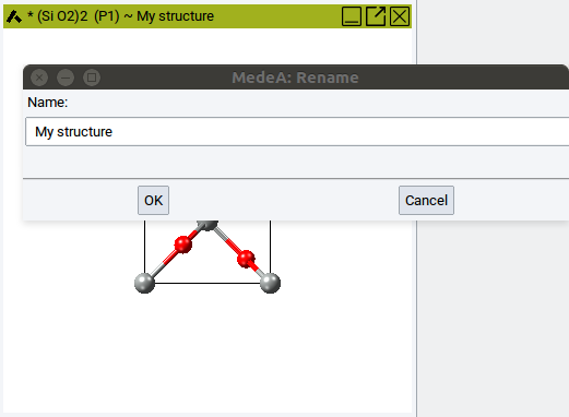
Simply enter a meaningful name and confirm with OK. The new name appears immediately in the title bar of the structure window.
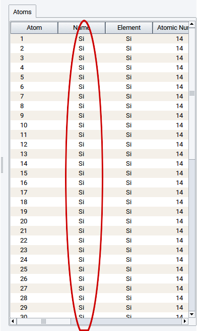
2.4.11. Automatically Rename Atoms
Whenever structures are imported from external resources, e.g. as VASP POSCAR files via File >> Open structure from disk, all atoms can have the same names:
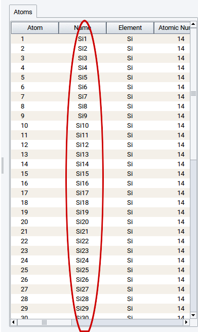
You can give all atoms different and distinguishable names using Edit >> Automatically rename atoms.
2.4.12. Create Copies of Structures
While building structures it is quite useful to keep copies of a structure prior to continued editing of the system. Creating copies of structures is sometimes also useful in case final structures have the same origin, i.e. the same parent structure.
Simply copy active structures via Edit >> Duplicate.
2.4.13. Molecular Builder
The MedeA Molecular Builder lets you create molecules, fragments, and polymer repeat units from scratch and combine them with bulk and/or surface systems. The resulting structures are ready for use with the MedeA compute engines VASP, GIBBS, LAMMPS, MOPAC, and Gaussian. In addition, you can use and expand a library of molecular fragments which are very useful building blocks when constructing more complex systems. Furthermore, you can predict particular thermophysical properties of small molecules and polymer repeat units with QSPR and P3C, respectively, i.e. based on group contribution and topological descriptor methods.
2.4.13.1. Getting Started
You can start the Molecular Builder without any active system via
- using the keyboard shortcut Crtl+M
- invoking File >> New non-periodic strucure
- invoking File >> New molecule from SMILES (for more information see Create New Structures)
Alternatively, you can also transform active periodic structures into molecular (non-periodic) structures via
- Edit >> Edit in molecular builder
- right-click >> * Edit in molecular builder
The Molecular Builder consists of a drawing area (canvas on the left) and the six tabs
- Insertion
- References
- Cell
- Charge/Spin
- P3C
- QSPR
To display a specific tab, simply click on the tab with the appropriate label.
Hint
If the Molecular Builder is opened via the keyboard shortcut Crtl+M or
File >> New non-preriodic strucure then only the empty canvas is
visible.
To visualize the tabs click on the icon or invoke
Edit >> Show Builder panel.
2.4.13.2. Main Features in Brief
As you start building, the drawing area displays the structure under construction. A right-click into a blank spot of the drawing area invokes the Context Menu in the Molecular Builder
When adding atoms to build up the molecule, the title bar of the Molecular Builder window displays the current stoichiometry of the active structure. An asterisk (*) indicates that you made changes to the structure but did not save these changes.
To start building a molecule from scratch, click on an element and coordination icon in the the Insertion tab. In doing so you “load” your pointer with the selected element and the shape of the pointer turns into a pencil. When the pointer has been loaded, click somewhere in the canvas to deposit an atom, connect atoms through their active bonds (stubs), or move the pointer over one of the existing bonds to highlight the bond in purple, followed by a click to drop an atom, thereby creating a bond.
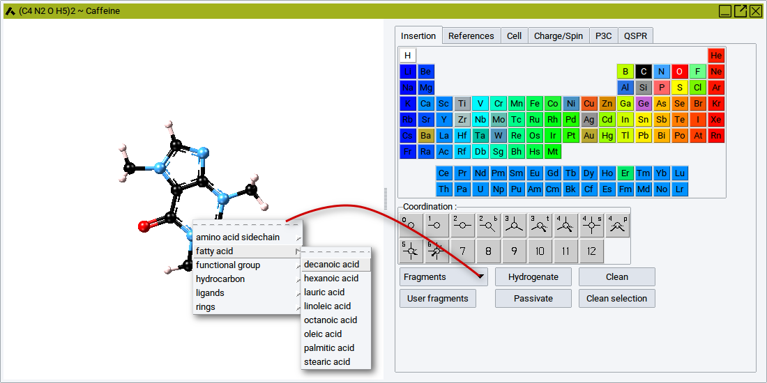
To load the pointer with a fragment, click on Fragments and select a fragment from the groups
- Amino acid side chains
- Fatty acids
- Functional groups
- Hydrocarbons,
- Ligands
- Rings
Once the pointer is loaded with a fragment it has the shape of a pencil. With the pencil pointer click somewhere in the canvas to deposit the selected fragment.
Note
One atom of the deposited fragment has an active bond which appears as a stub.
After you have modified the fragment you can save this fragment, with the context menu: right-click somewhere in the drawing area >> Save as Fragment.
Note
To save molecules as fragments they must have one active bond.
In case molecules do not have any active bond you can add one simply by right-clicking on the atom that should have an active bond >> Atom >> Add Active Bond.
Fragments, i.e. molecules with an active bonds, and also molecules with more active bonds can be easily connected with other atoms and fragments, respectively, To connect fragments with another atom, first select an element and a Coordination from the Insertion tab, then move the pencil pointer over the active bond (should turn into purple), and finally click on the bond. Depending on the selected element and coordinaton, the added atom has zero, one, or more extra active bonds to connect with other atoms and fragments, respectively.
To connect fragments with another fragment, first select a fragment via the Fragments selection bar of the Insertion tab, then move the pencil pointer over the active bond (should turn into purple), and finally click on the bond.
Note
Moving the pointer holding down the left pointer key lets you rotate the added fragment around the newly formed bond.
The options and features to position and visualize structures are almost identical to those described in the section Structure Positioning and Visualization. Relevant features are accessible via the View menu in the main menu bar and the icon bar below the main menu bar.
The created molecular structures can be used directly to start MedeA jobs with the MOPAC GUI and the Gaussian GUI. The features of the MOPAC GUI and the Gaussian GUI are described in the manual sections MOPAC 2009/2012/2016 and MedeA Gaussian, respectively.
Hint
Every structure used to start a MedeA job is automatically stored on the JobServer and can be opened via File >> Open structure from job.
It is also possible is to save molecular structues in structure lists. Saving structures in structure lists is described in chapter MedeA HT of the MedeA manual.
In case you want to save a structure as a file to disk, export a molecule with File >> Export to file The supported file formats are visible in the selection bar Files of type:.
To convert a molecular structure without periodic boundary conditions back to a periodic system invoke Edit >> Create a periodic copy.
Hint
MedeA jobs with VASP, LAMMPS, and GIBBS require structures in simulation cells, i.e. with periodic boundary conditions.
2.4.13.3. Context Menu in the Molecular Builder
In general, the context menu of a molecular structure window is opened with a right-click somewhere in the drawing area. However, the displayed menu items depend on whether the pointer is positioned on an atom, a bond, or empty space (anywhere else in the structure window).
Transferring Atoms and Fragments Between Structures
With the following menu items it is possible the transfer entities (single atoms, groups of atoms, molecules, and fragments) from one structure into other structures.
- Paste: introduce previously copied atoms
- Copy full structure: creates a copy of the entire structure, including bond information, atom type, and other atomic properties
- Copy selection: creates a copy of selected atoms of a structure, including bond information, atom type, and other atomic properties
Descriptions of all other items of the context menu are as follows:
Modify Internal Coordinates
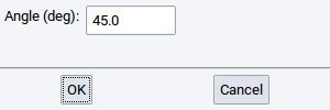
With the Internal coordinates menu item you can interactively change internal coordinates of molecules such as dihedrals (torsional angles), bond angles, and bond lengths.
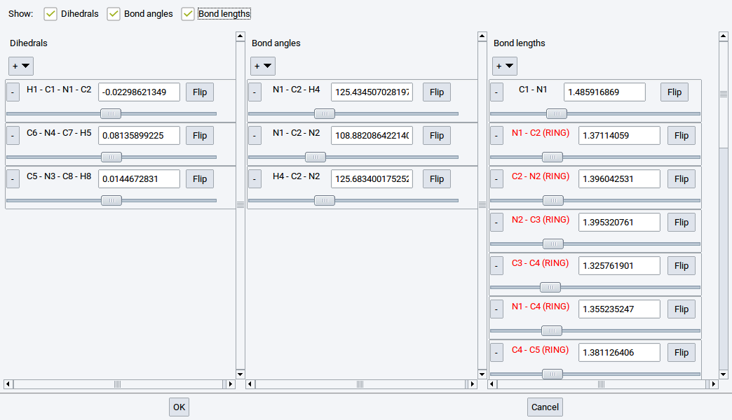
Either use the sliders to reduce or increase the values of particular coordinates one-by-one. Alternatively, enter the new values in the number fields; the units are \({\mathring{\mathrm{A}}}\) for distances and degrees for angles. Molecular structures immediately respond to the changes. Add or remove certain internal coordinates with the selectors + and +, respectively. Internal coordinates that cannot be modified independently, i.e. without affecting other internal coordinates due to structural restrictions, are highlighed in red.
To confirm all modifications, close the dialog with OK. To discard all structural modifications, close the dialog with Cancel.
Hint
To reset all structural modifications in case the dialog was accidently closed with OK click on the Clean button of the Insertion tab.
Other features of the Molecular Builder used to modify internal coordinates of molecules require selected atoms.
Note
The following three menu items appear only in the main context menu if a particular number of atoms is selected.
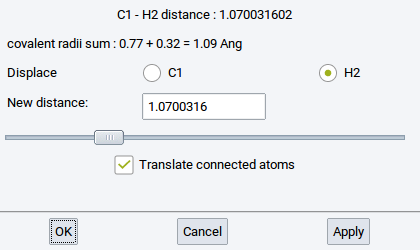
Distance: Change the distance between two selected and connected (bonded) atoms
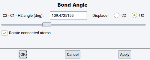
Bond Angle: Change the angle between three selected and connected (bonded) atoms
Dihedral: Change the torsional angle between four selected and connected (bonded) atoms
Action Modes
With the Mode menu item change the action mode.
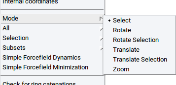
- Select: Select atom(s) (by clicking on individual atoms or dragging the pointer over a relevant region with atoms); selected atoms are highlighted in white
- Rotate: In this mode the entire structure can be rotated
- Rotate Selection: In this mode only selected atoms of the structure can be rotated
- Translate: In this mode the entire structure can be translated (moved)
- Translate Selection: In this mode only selected atoms of the structure can be translated (moved)
- Zoom: Zoom in/out by moving the pointer or using the arrow keys of the keyboard
Position all Molecules in the Drawing Area
With the menu item All collectively move all molecules, fragments, atoms, etc. that are present in the drawing area of the Molecular Builder
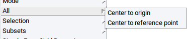
- Center to origin: Move the common center of mass of all structures to the center of the
coordinate system, i.e. x = y = z = 0.0 (the center of the coordinate system can be visualized with the
axes icon and is at the intersection of the colored cylinders
- Center to reference point: Move the common center of mass of all structures to a reference point that is defined in the References tab of the Molecular Builder.
Selection of Atoms and Fragments
With the menu item Selection either select all atoms of a structure, clear atom selections, or modify structures based on the selected atoms.
Note
All the following items - except Select all (Crtl-A) require previously selected atoms!
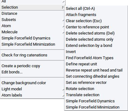
Select all (Ctrl-A): Selects all atoms; can be also invoked with the key-stroke Ctrl-A
Attach fragments: bind atoms or molecules to previously selected atoms (more information is provided in the section Attach Fragments Tab)
Clear selection (Esc): Unselect any selection; can be also invoked with the Esc key of the keyboard
Center to reference point: Move the common center of mass of the selected atoms to a reference point that is defined in the References tab of the Molecular Builder
Delete selected atoms (Del): Erases selected atoms and bonds to connected atoms; can be invoked with the Del key of the keyboard
Delete selected atoms only: Erases selected atoms but maintains half bonds as stubs (active bonds) to connect other atoms or fragments
Extend selection by a bond: Expands selections to neighboring atoms and atoms connected with bonds
Invert: select all un-selected atoms and de-select all previously selected atoms
Find Forcefield Atom Types: Assign forcefield (FF) atom types to selected atoms only based on the selected forcefield (check the selected forcefield with the main menu item Forcefields >> Choose)
Rotate selection: Rotate selected atoms around the Reference vector which is defined in the References tab of the Molecular Builder
The units of rotation angles are degrees.
Translate selection: Translate selected atoms parallel to the Reference vector which is defined in the References tab of the Molecular Builder; the translation distance is defined by the length of the Reference vector
Simple Forcefield Dynamics: Evolves selected atoms in 100 molecular dynamics steps, employing a simple forcefield
Simple Forcefield Minimization: relaxes selected atoms, employing a simple forcefield
Note
The following menu items appear only if a particular number of atoms are selected.
Define repeat unit: If two non-hydrogen atoms are selected you can set the head and tail of a repeat unit (polymer ‘monomer’) that you can then use in the Polymer Builder to create macromolecules
Reverse repeat unit head and tail: If the head and tail atoms of a repeat unit are selected swap the head and tail of the repeat unit
Set connecting dihedral angles: Modify all torsional angles between two selected atoms. Requires that the two selected atoms are separated by two or more other atoms.
Note
This is a very useful feature to set torsional angles in a polymer chain or in any other large molecule.
Set as reference vector: Define a reference vector with two selected atoms; reference vectors are useful to translate and rotate, respectively, selected atoms along a certain direction and around a particular axis, respectively
Set normal as reference vector: If you have selected three atoms, then define a reference vector as the normal of the surface that is spanned by the three atoms; reference vectors are useful to translate and rotate, respectively, selected atoms along a certain direction and around a particular axis, respectively
Note
All the following items require enabling the mixed visualization mode (click on the icon )
- Display as CPK: visualize selected atoms as spheres
- Display as Ball & Sticks: visualize selected atoms as balls connected with sticks
- Display as Sticks: visualize selected atoms as sticks only
- Display as Lines: visualize selected atoms as lines
- Hide: do not show selected atoms
Subsets
Within MedeA subsets are sets of atoms that belong to particular molecules and fragments, are of the same element, have the same forcefield atom type, are selected at the same time, etc. Subsets are very useful and required, for example, to graphically distinguish groups of atoms with different properties using different visualization styles, to analyze results, or to post-process data from calculations. With the Subset context menu item you can create and edit subsets.
Note
All the following items - except Create… or Create subset from selection… require previously created subsets or previously selected atoms, respectively.
Create…: opens a dialog to specify how a subset should be created (for more information see the section Subsets)
Create subset from selection…: opens a new window to define the name of the subset (for more information see the section Subsets)
Delete atoms in subset: Delete all atoms that form the subset and also the subset itself
Select atoms in subset: Select all atoms that define a subset
Delete subset: Delete the subset definition but keep the atoms
Combine subsets: Create a new subset from two or more subsets
- Union: the new subset encompasses all atoms that belong to the subets that should be combined
- Intersection: the new subset encompasses only atoms that belong to all of the subsets that should be combined
- +: add empty entries/fields () to define more subsets that should be comnined
- -: remove empty and filled fields from the collection of subsets that should be combined
- Update first subset: let the first subset be the combination of all subsets
- Create new subset: : Combine all relevant subsets in a new subset; define
the name in the empty fields (e.g. subset3)
- Remove initial subsets after combination:: Delete the definition of subsers that should be combined
Attach Fragments in subset: Connect molecular fragments to atoms of a subset (more information is provided in the section Attach Fragments)
Subset summary: Show a summary of existing subsets in an separate window
Edit Atom Properties
The Atom context menu item appears upon right-clicking with the pointer over an atom
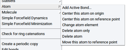
- Add Active Bond…: Add a half bond (stub) to an atom; the direction of the bond is perpendicular to the screen
- Center this atom to origin: Move the atom and all connected atoms to the center of the
coordinate system, i.e. x = y = z = 0.0 (the center of the coordinate system can be visualized with the
axes icon and is the intersection of the colored cylinders
- Center this atom to reference point: Translate this atom and all connected atoms to a reference point that is defined in the References tab of the Molecular Builder
- Change atom element: Replace the element of this atom by the element selected in the periodic system of the elements in the Insertion tab; the selected coordination is ignored
- Delete atom only: Delete this atom but maintain the half bonds (stubs) of the connected atoms as active bonds
- Delete atom: Delete this atom and all bonds to connected atoms
- Move this atom to reference point: Move only this atom (not the other atoms) to a reference point that is defined in the References tab of the Molecular Builder
Edit Molecule Properties
The Molecule context menu item appears upon right-clicking with the pointer over an atom
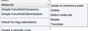
Center to reference point: Translate the center of mass of this molecule to a reference point that is defined in the References tab of the Molecular Builder
Delete: Delete this molecule
Select molecule: Select this entire molecule
Rotate: Rotate this molecule around the Reference vector which is defined in the References tab of the Molecular Builder
The unit of the rotation angle is degrees.
Translate: Translate this molecule parallel to the Reference vector which is defined in the References tab of the Molecular Builder; the translation distance is defined by the length of the Reference vector
Create or Delete Bonds
Note
The following menu item only appears if the structure has bonds and if the right-click is over a bond.
- Delete bond…: Deletes the bond underneath the pointer
Note
The following menu item only appears if two atoms are selected.
- Create bond: Create a bond between two selected atoms.
Modify Bond Order
Note
The following menu items only appear if the structure has bonds and if the right-click is over a bond.
With the menu item Bond Order you can change the order of the bond underneath the pointer
- Single: Define a single bond
- Aromatic/Partial Double: Define an aromatic or partial double bond
- Double: Define a double bond
- Triple: Define a triple bond
Check Macromolecules
- Check for ring catenation: Determine whether molecule bonds/chains go through rings and loops of other molecules (very important to avoid ring catenation, especially in realistic polymer and polyaromatic models)
Create Periodic Structures
- Creare periodic copy: Put all molecules, fragments, atoms, etc. in the drawing area in a simulation cell with periodic boundary conditions, such that the resulting structure can be used in calculations with VASP, LAMMPS, and GIBBS; the cell dimensions are defined in the Cell tab of the Molecular Builder
- Edit bonds: Opens the Edit Bonds dialog and lets you recalculate the bonds
Increase Graphical Contrast
- Change background color: Changes the background color of all structure windows (for more information read the Section Define Background Color)
Illumination of Structures
With the menu item Light model define how structures are illuminated.
- Single light source
- 3 light sources, soft
- 3 light sources, shiny
Tag Atoms With Labels
With the menu item Atom labels define in sub-menus which atomic properties should be displayed as labels next to each atom
- Atomic number: Display the atom index in the structure
- Calculated charge: Display the charge that was calculated with e.g. VASP
- Atomic symbol: Display element symbol
- Forcefield atom type: Display assigned forcefield atom type
- Forcefield charge on atom: Display assigned forcefield atom charge
- Fractional coordinates: Display fractional coordinates of atoms
- Name: Display assigned names of atoms
- Number of bonds: Display number of connections to other atoms
- Point: Display points of atoms
- Site: Display crystallographic site of atoms within the assigned space group symmetry
- Spin: Display magnetic moment of atoms
- Wyckoff position: Display crystallographic Wyckoff position of atoms within the assigned space group symmetry
2.4.13.4. Insertion Tab
Within the insertion tab you can select elements to add to structures in the drawing area and their coordination. When selecting an element, its default coordination is highlighted in the section Coordination:
Example: For Oxygen, the default coordination of 2 is highlighted. You can change the coordination by selecting, e.g. 1
An element with coordination number \(n\) will be drawn with \(n\) active bonds. Note that an active bond is just a visual aid (depicted as a stub) serving to make a connection to other atoms. Using active bonds you can build up realistic molecular structures with a few pointer clicks.
Hint
A structure with at least one active bond is considered to be a fragment. A fragment can be saved to the fragment library for later reuse as a molecular building block.
A molecular structure without any active bonds is considered a complete molecule. To save a molecule, export it to disk or convert it into a periodic model.
Further features present in the Insertion tab are:
Fragments: With this selector you access to about 100 different fragments which are categorized into amino acid side chains, fatty acids, functional groups; hydrocarbons, ligands, and rings.
User fragments: With this selector you have access to your fragment library
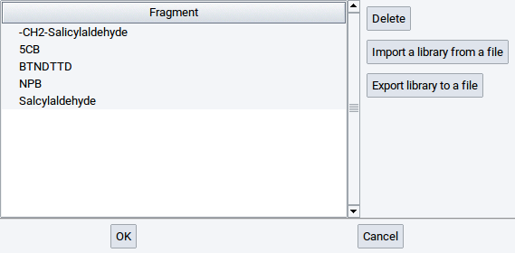
Any fragment (a molecule with one active bond) in the drawing area can be added to the your fragment library with the context menu (right-click >> Save as fragment)
With a click on a record in the list of fragments you select a fragment. To load the pointer with this fragment confirm with OK. You can also :highlightgray:`Delete the highlighted fragment, Import a library from a file, and Export library to file. With the latter two options you can share fragment libraries with colleagues, e.g. transferring custom fragments between MedeA installations.
Hydrogenate: With this option automatically add hydrogen atoms to all active bonds
Passivate Saturate all active bonds with the element that is activated in the periodic system of the elements or an active fragment.
Clean: This option relaxes molecular structures with a simple forcefield to obtain a reasonable initial structure for further modifications or calculations.
Clean selection: This option relaxes only selected atoms in the drawing area with a simple forcefield.
Note
Molecules are relaxed based on the chemical connectivity and a forcefield that combines generic non-bonded interactions (Lennard-Jones potential) with atom-specific parameters for bonds, angles, and dihedrals.
2.4.13.5. References Tab
The References panel lets you define a reference point and a reference vector to perform actions such as Translate, Rotate, Center single atoms, a group of selected atoms, individual molecules, or all molecules in the drawing area.
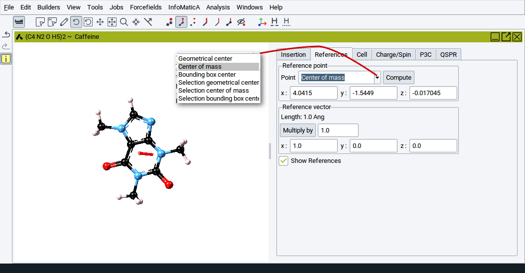
For example, you can define a reference point to be the center of mass of the molecule or a selection of atoms. You can then translate the molecule such that its geometrical center comes to lie on the center of mass. Alternatively you can define a reference point and vector and translate a group of atoms or a molecule around the axis defined by the point and vector.
Reference point
You can type in the values for the x:, y:, and z: coordinates, respectively, of a point (press the Return key of the keyboard to confirm) or select special points from the list:
- Geometrical center: geometrical center of all atoms in the drawing area
- Center of Mass: center of mass of all atoms in the drawing area
- Bounding box center: center of smallest possible box that encompasses all atoms
- Selection geometrical center: geometric center of the selected atoms
- Selection center of mass: center of mass of the selected atoms
- Selection bounding box center: center of the smallest box that encompasses all selected atoms
To set the new reference point click on Compute.
Reference vector
To define a vector, simply input values for the x:, y:, and z: coordinates of the end point of the vector. The offset or starting point of the vector is defined by the reference point. Alternatively you can select two atoms in the drawing area and invoke right-click >> Selection >> Set as reference vector. The values of the x:, y:, and z: coordinates for the reference point and reference vector, respectively, are adapted accordingly. Also, you can scale the vector by setting Multiply by to a value other than 1.0.
Check the box Show References to display the reference point and vector (red bullet and red cylinder in drawing area).
Hint
Note that atoms or bonds may hide the reference point and vector.
2.4.13.6. Cell Tab
In the Cell tab define the dimension of the cell that surrounds the molecules in the drawing area. When converted to a periodic structure this cell will be the periodic unit cell and simulation cell, respectively, in which structures are located.
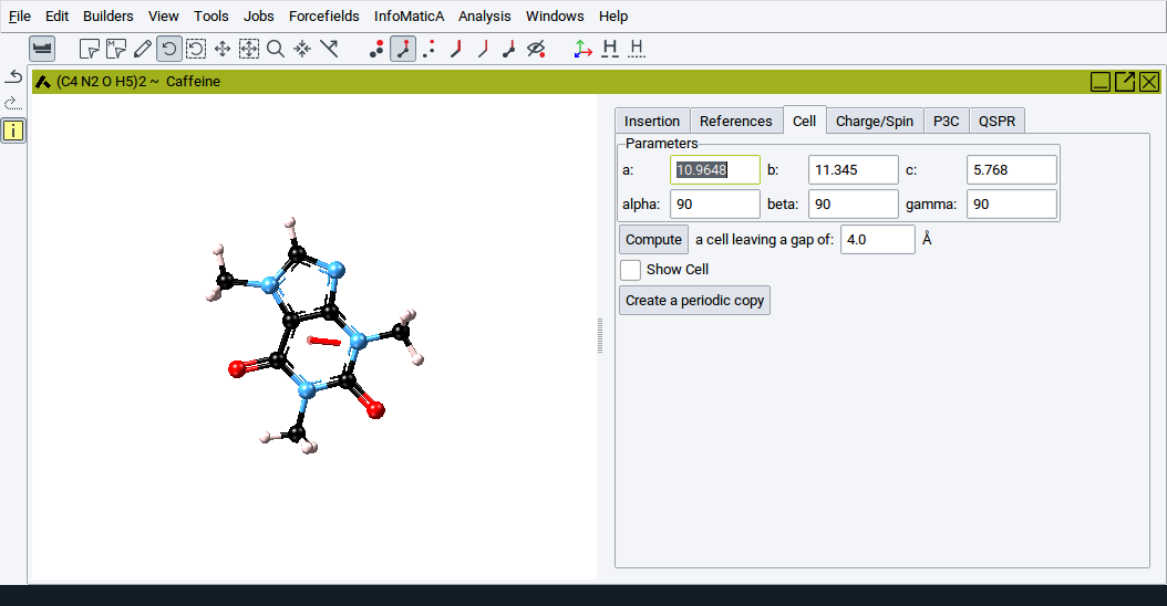
When converting a periodic structure into a molecular structure the original cell parameters are maintained and shown by default.
However, you can either explicitly define the cell parameters a:, b:, c:, alpha:, beta:, and gamma:. Alternatively, define a void region (a value for the option a cell leaving a gap of around the molecules and leave it to the builder to handle cell dimensions by clicking on Compute.
To show the current cell add a check-mark to the option Show Cell.
If you want to convert a structure to a periodic model click on Create a periodic copy.
2.4.13.7. Charge/Spin Tab
The Charge/Spin tab allows you to set the total charge and spin of a system used in calculations with MOPAC and Gaussian, respectively.
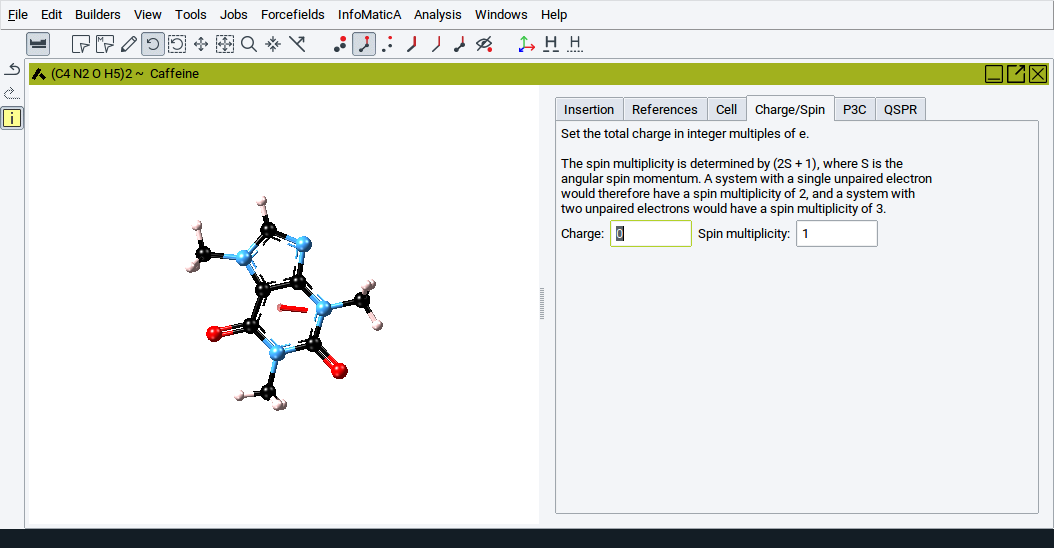
The total charge is expressed in units of electrons and the spin is expressed via the spin multiplicity, \(2 S + 1\), whereby \(S\) is the angular spin momentum. For a given value of \(S\) the spin multiplicity determines the number of degenerate wavefunctions which differ only in the orientation of their angular spin momenta.
2.4.13.8. P3C Tab
This tab displays thermo-physical properties and structural descriptors that are calculated with MedeA P3C (Polymer Property Prediction using Correlations). This approach employs correlations to predict polymer properties based on the chemical topology of its constituent repeat units.
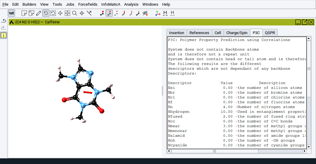
More information is provided in Section MedeA P3C:Polymer Property Prediction Using Correlations.
2.4.13.9. QSPR Tab
This tab displays thermo-physical properties and structural descriptors that are calculated with MedeA QSPR (Quantitative Structure Property Relationships). The approach employs correlations based on the chemical groups that constitute an organic molecule.
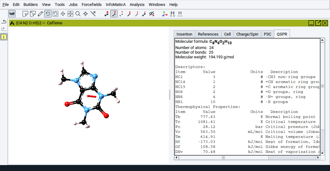
More information is provided in Section MedeA QSPR: Property Prediction Using Group Contributions
2.4.14. Attach Fragments
Using the Attach Fragments dialog you can quickly attach atoms and molecular fragments to atoms of amorphous and crystalline bulk structures, surface atoms of slab models, clusters, etc.
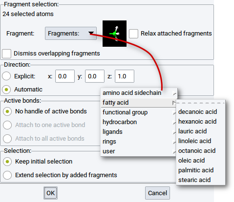
The Attach Fragments dialog is also accessible via the context menu items
A requirement to attach fragments is that atoms, to which other atoms or molecular fragments should be attached, must either be selected or part of subsets.
The first line in the section Fragment selection: indicates the number of atoms to which fragments will be attached. For example, in the above screenshot the line is 24 selected atoms, which implies that one fragment will be attached to 24 atoms of the active structure.
With atoms selected, choose the fragment that should be attached from the Fragments: selection bar. The fragment library consists of about 100 different molecular residuals which are categorized into
- Amino acid side chains
- Fatty acids
- Functional groups
- Hydrocarbons,
- Ligands
- Rings
and also User defined fragments.
The selected fragment is displayed in the small image next to the Fragments: selection bar. To minimize steric repulsion between the attached fragments and the host structure, tick (enable) the option Relax attached fragments. In case you want to avoid any overlap among added fragments and with the host structure tick (enable) the option Dismiss overlapping fragments.
With the options in the Direction: section you can attach fragments such that their backbone is parallel to an Explicit: spatial direction defined by the vectorial components x:, y:, and z:. However, by default the direction of the backbones of fragments is automatically defined by the algorithm of the Attach Fragments feature.
The most general case is that only the option No handle of active bonds is enabled. With this option only one fragment is attached to each selected atom. In molecular (non-periodic) structures atoms can have one or more active bonds (stubs without any connections to other atoms). In such cases the other two options
- Attach on one active bond
- Attach on each active bond
can be checked (enabled). The first option of the two implies that among several active bonds of the selected atoms a fragment is attached to only one active bond. If the second option is enabled then fragments are attached to all active bonds of the selected atoms.
With the options in the Selection: section you can define whether to maintain the initial selection of the atoms to which atoms are attached (keep the initial selection) or to extend the selection to the atoms of the attached fragments (Add fragments to the selection).
As illustrated in the image below, the feature Attach Fragments lets you attach water molecules to atoms of the two images of a slab model for the Al2O3 (001) surface with four steps:
- Select relevant atoms to which water molecules should be attached
- right-click >> Selection >> Attach fragments
- Choose water from the fragment library (Fragments >> ligands >> water)
- Confirm with OK
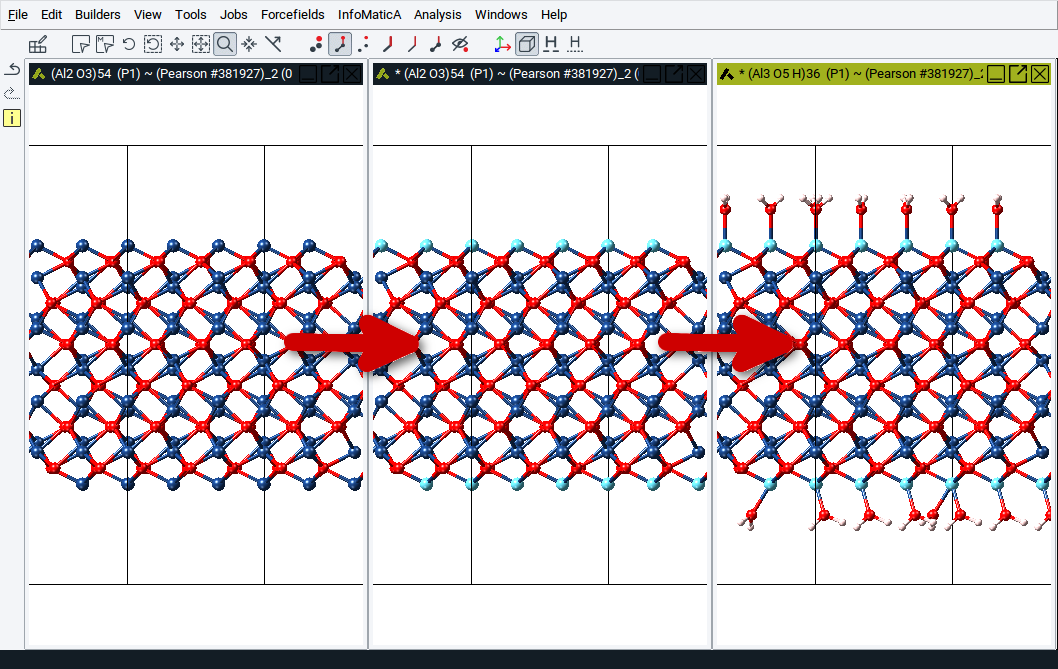
| [1] | C Bradford Barber, David P Dobkin, and Hannu Huhdanpaa, “The Quickhull Algorithm for Convex Hulls,” ACM Transactions on Mathematical Software 22, no. 4 (December 1, 1996): 469-483. |
| download: | pdf |
|---|